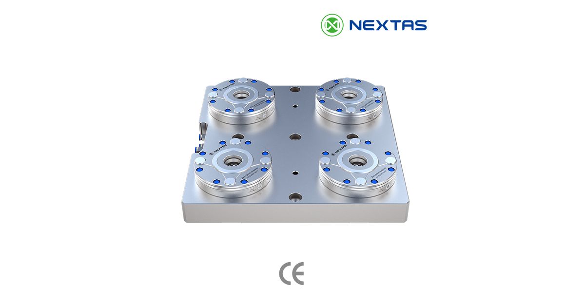
A 25-second view of a NEXTAS side-inlet zero-point arrangement. It shows the port direction but does not prove load, repeatability or production fit.
Choose a side inlet when an existing table or subplate cannot route release air from below, or when side service access is clearly better. It changes where the air line enters the receiver. It does not fix a weak plate, poor support or an undersized receiver layout.
This makes side inlet a narrow retrofit choice. The first work is not picking the largest receiver. It is drawing the table, port, hose, guard, fixture mass, centre of gravity and cutting load in one view.
Plain answer
Use bottom inlet when the table can hide and protect the air route. Use side inlet when through-table routing is not practical and the side hose can be guarded, serviced and kept clear of every moving path.
Side inlet solves routing, not load
A large part may need several receivers, a thicker subplate or more support. Moving the air port to the side does not change those needs. Receiver count and spacing still follow the full fixture load and cut direction.
Do not use fixture mass as the only check. Add the part mass, centre of gravity, lifting motion, acceleration, overhang and cutting moment. A force that acts far above the plate can create a large turning load even when the mass looks modest.
The same rule applies to a horizontal machining centre, tombstone or rotary table. Machine type does not make a side-inlet setup suitable by itself.
Does the existing table favor side or bottom entry?
| Question | Bottom inlet may fit when | Side inlet may fit when |
|---|---|---|
| Can the table carry an internal air route? | Ports can be machined and sealed without weakening the approved table or plate. | Through-table work is blocked, risky or not allowed. |
| Where is the line protected? | The route stays below the working face. | A side guard can keep the hose clear of chips and motion. |
| How is it serviced? | Bottom access is available without a major strip-down. | Side fittings can be reached without lifting the full stack. |
| Will the cell automate later? | The planned valves and signals suit the hidden route. | The side route can be secured and proven through every cell movement. |
Ask the machine or table maker before drilling a supplied table. If a separate subplate is used, review its thickness, flatness, seals, mounting screws and support. The air route must not create a weak section or a leak path.
(7)%20(1).png?updatedAt=1754553736043)
Receiver data is not full-layout capacity
The current NEXTAS zero-point product page publishes three V1 receiver sizes in one family. It lists repeat positioning of 0.003 mm or less for each interface.
| Receiver | Clamping force | Lift load | Still to confirm |
|---|---|---|---|
| NT-S200P120V1 | 12 kN | 100 kg | Port direction, layout, moment, cut load and selected drawing |
| NT-S200P160V1 | 18 kN | 250 kg | Port direction, layout, moment, cut load and selected drawing |
| NT-S200P195V1 | 40 kN | 300 kg | Port direction, layout, moment, cut load and selected drawing |
Lift load is not the allowed payload for every application. It does not include the full effect of centre of gravity, receiver spacing, cut direction, machine motion or a dynamic lift. Treat it as one model value inside a wider load review.
The published family also describes pneumatic release, mechanical self-locking, hardened stainless parts, datum cleaning and air-tightness checks. Confirm which functions and port direction belong to the exact ordered model. A family page is not a substitute for that model drawing.

Where can the hoses actually run?
Show the full line from valve to receiver. Mark the bend radius, fitting access and strain relief. Then add the paths of the spindle, door, pallet, crane, fork, robot and operator.
- Keep fittings away from direct chip and coolant flow.
- Use a guard where a dropped part or tool could hit the line.
- Support the hose so loading does not pull on the port.
- Leave room to disconnect and test each receiver.
- Label the line and receiver so service staff can trace faults.
For several receivers, also check that each branch gets the required pressure and release flow. Do not assume that matching hose lengths will make every station act at the same time. Test the complete circuit.
Commissioning: one receiver before the full station
Begin with the selected receiver and real supply. Check pressure at the module, leaks, release motion and the cleaning step. Then mount the actual pallet or fixture and repeat the load-clean-seat cycle.
After that, test the whole layout. Measure the points that matter to the process. Include an uneven load, the expected centre of gravity and the real handling route where safe to do so.
If the station connects to a machine or robot, define the normal state signals and the fault response. A normal clamp signal can block a process step. It does not replace the safety functions set by the complete cell risk review.
- Confirm the selected model and port drawing.
- Pressure-test every line and branch.
- Run repeated clean, release and reseat cycles.
- Check the full fixture at the buyer-set points.
- Create a low-pressure or missing-seat fault in a controlled test.
- Confirm who may reset the fault and how the station restarts.
What can the 25-second demonstration prove?
The video at the top shows that NEXTAS has built a side-inlet arrangement. It helps a buyer see the port and general layout. It does not identify the receiver model, test load, pressure, repeatability result or production history.
Use the video to ask better questions. Use the selected drawing, model data and acceptance record to make the buying decision.
The retrofit envelope engineering needs
Send the machine table or subplate drawing and clear photos. Add the available footprint, stack height, proposed side port, fixture and part mass, centre of gravity, main cut direction and receiver layout.
Also send the available air pressure and air-quality plan, hose route, valve concept, signals and buyer-set reseat limit. NEXTAS can then review the routing idea and list the checks that remain open.
No safe bottom air route?
Check the air path before machining
Send the table, subplate, load and full hose path. The review should separate receiver data from the checks required for the complete station.
Frequently Asked Questions
What problem does a side-inlet zero-point receiver solve?
It gives the release-air line a side entry when bottom routing is not practical or side service access is better. It does not add load capacity or fix a weak plate by itself.
Is side inlet always better for a large horizontal machining centre?
No. Choose the inlet from the real table, subplate, hose path, service access and moving envelope. The machine type and part size do not decide the route on their own.
Does the published lift load equal the allowed fixture payload?
No. Lift load is one receiver value. The full layout must also include part and fixture mass, centre of gravity, receiver spacing, cutting moment, machine motion and handling loads.
Can several receivers clamp one large fixture?
They may be used in a reviewed multi-receiver layout. The plate, spacing, branch flow, pressure, release timing, load path and clean-reseat result all need to be checked together.
What must pass before a side-inlet retrofit is released?
Confirm the model and port drawing, pressure-test the circuit, run clean-release-reseat cycles, measure the loaded fixture, test planned faults and approve the reset and restart steps.
Keep exploring
Related Articles
Continue with closely matched guides on zero-point selection, repeatability, plate layout and retrofit planning.

Zero-Point System RFQ: Model, Interface and Acceptance
Turn a zero-point plan into an exact-model RFQ. Check interface drawings, load and support, pull-stud fit, air and signals, documents and acceptance.
Read article →
High-Performance Zero-Point Plates: When the Premium Is Worth It
Decide when a premium zero-point plate is justified by checking the selected model, load path, support count, stack height, mounting, and release tests.
Read article →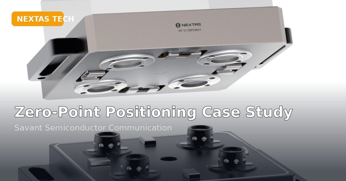
Zero-Point Positioning for Semiconductor Equipment: How to Qualify Datum Transfer
Separate interface reseating from cross-station shift and qualify the datum from CNC machining to CMM inspection.
Read article →Match the hardware
Related Products
These product pages are the most direct next step if you are comparing zero-point hardware, plate formats and integration options.
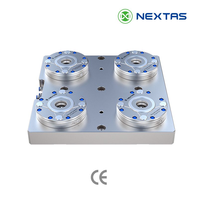
Zero-Point Clamping Systems
MFG zero-point systems for CNC automation, pallets and fixtures, with tapered positioning, mechanical self-locking and repeatability up to ≤0.003 mm.
View product →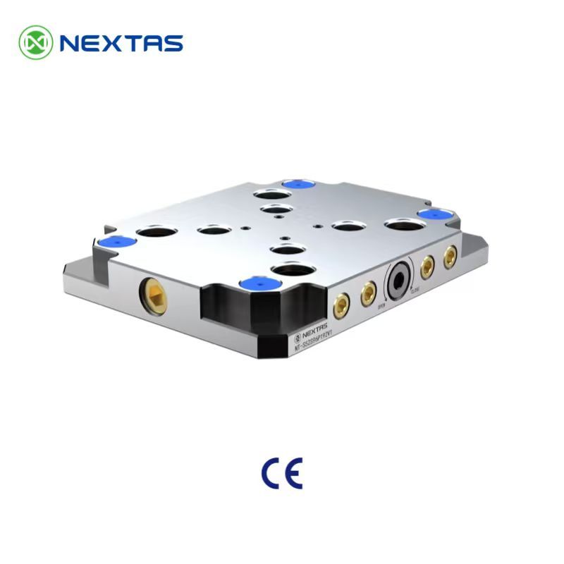
Quick-Change Zero-Point Clamping Plate
Quick-change zero-point clamping plates in 52 mm and 96 mm modular formats for vises, pallets and fixtures, with fixed indexing and fast manual unlocking.
View product →Compact Automation Datum System for Pallets & Fixture Carriers
Compact automation datum system for pallets and fixture carriers, with BDS A024 / B024 interfaces, <0.003 mm repeatability and 60,000 N clamping force.
View product →Evaluating a zero-point system?
Send us your pallet size, mounting pattern, repeatability target, and automation plan. We can help compare pull-down force, chip protection, and integration details before you commit.
Discuss Zero-Point Integration →