EDM / WEDM Datum Transfer

E-Series EDM Automation Chuck for WEDM & Inspection Transfer

ITS-style datum chuck platform for EDM, WEDM, grinding, CMM and electrode preparation workflows.

Use the E-Series when the real need is one repeatable reference that follows electrodes or precision parts across EDM-related stations. Instead of reading the page as one long list of Model 100 variants, start by locking the holder standard, transfer chain, and air-routing limits that decide which chuck style fits.

The E-Series is intended for ITS-style electrode and precision-part transfer across EDM, WEDM, preparation, grinding, and inspection stations. Select it only after the exact holder, adaptive spigot, chuck orientation, mounting, stack height, loads, air circuit, and acceptance method are verified for every station; a shared family name does not prove interchangeability. Compare the R-Series when the required machine-side interface follows a System 3R-style route.

Engineering boundary: <0.003 mm is catalog-listed component data for NT-S100P100V1, NT-S100P100V2, NT-S100P100V3 and NT-S100P80V1, not a complete-process guarantee. ITS 50 / ER-036345-style fit, air-loss behavior and automation suitability require the approved model drawing plus verification of holder and spigot geometry, mounting, load and orientation, pneumatic circuit, sensing, safety-related controls, and the complete machine/cell risk assessment.

ITS-style holder workflow
EDM, WEDM, grinding & CMM
Published <0.003 mm · four named models
Lead time: Confirmed after drawing, quantity and scope review MOQ: 1 set Payment: T/T · L/C Quality documents scoped at RFQ MIC Audited Supplier

Best fit

Choose this route when one datum reference must follow the EDM chain

Best for electrode and precision-part workflows that need repeatable transfer between EDM, WEDM, grinding, presetting, and inspection.

Compare first

Check holder standard, chuck orientation, and air access

That usually decides whether a standard pneumatic, side-vertical, or right-angle layout is the cleanest fit before model-by-model comparison.

Go next

Jump straight to the decision section you need

Use the shortcuts below when the real bottleneck is selection, integration, or maintenance planning.

Models, Specifications & Fit

Current product data describes mechanical self-locking clamping with pneumatic release on the four listed models. Confirm the exact model drawing, holder and spigot, load direction, pneumatic circuit, air-loss state, monitoring, and acceptance method; installed datum transfer, changeover, and automation results require FAT/SAT validation in the complete process.

Detailed view of the E-Series Chuck clamping mechanism

Construction, cleaning & options

The catalogue lists hardened stainless-steel construction. Cleaning, airtightness monitoring, internal passages, sealing, and port functions can depend on the selected model and circuit; confirm the approved drawing, manual, environment, and order scope before release.

Technical Specifications

Catalogue-aligned data for the four currently listed E-Series models. Values describe the named component under its specified conditions; they are not blanket limits or guarantees for the holder stack, robot payload, machining load, cross-machine datum, or finished process.

Technical Specifications — technical data
ParameterCatalog-listed variants
Model familyNT-S100P100V1 / NT-S100P100V2 / NT-S100P100V3 / NT-S100P80V1
Positioning conceptMechanical self-locking datum chuck with pneumatic release
Repeat positioning accuracy<0.003 mm
Clamping force>6,000 N (NT-S100P100V1 / V2 / V3), 4,000 N (NT-S100P80V1)
Clamping load15 kg listed for NT-S100P80V1
Operating pressure0.5–0.8 MPa
Adaptive spigot no.NT-S200P55V2 is the catalogue-associated spigot reference; verify the exact chuck model, revision, holder geometry, and approved drawing.
MaterialHardened stainless steel
Weight range2.0 kg / 5.3 kg / 7.1 kg / 17.7 kg depending on variant
Technical Specifications — technical data
ModelConfigurationRepeatabilityClampingPressureWeight
NT-S100P100V1Model 100 Pneumatic Chuck<0.003 mm>6,000 N0.5–0.8 MPa5.3 kg
NT-S100P100V2Model 100 Side Vertical Pneumatic Chuck<0.003 mm>6,000 N0.5–0.8 MPa7.1 kg
NT-S100P100V3Model 100 Right Angle Pneumatic Chuck<0.003 mm>6,000 N0.5–0.8 MPa17.7 kg
NT-S100P80V1EDM Pneumatic Chuck<0.003 mm4,000 N / 15 kg load0.5–0.8 MPa2.0 kg

Model 100 variant matrix

Accessory plates, spigots & holder-side hardware

The catalogue lists positioning plates and a clamping-spigot reference alongside the chuck bodies. Treat each as a candidate order component and verify its exact model, revision, geometry, mounting, and approved interface drawing before release.

Accessory plates, spigots & holder-side hardware — technical data
Accessory Model Configuration / detail Material Weight
Powerful positioning plateNT-S100P90V1Each positioning plate contains 8 × M8 supporting feet.Hardened stainless steel0.15 kg
Powerful positioning plateNT-S100P90V24 × M8 support feet + 4 × M5 screws.Hardened stainless steel0.11 kg
50 positioning plateNT-S100P50V1Each positioning plate contains 4 × M8 support feet.Hardened stainless steel0.03 kg
Matching clamping spigotNT-S200P55V2Catalogue-associated spigot candidate for Model 100 configurations; verify the exact chuck model, revision, holder geometry, and approved drawing before order release.Hardened stainless steel0.08 kg

Why this matters: component repeatability alone does not qualify the transfer chain. Release the order only after the holder-side plate, spigot geometry, mounting stack, loads, environment, and measurement method are verified for every bench, machine, and inspection station.

System Selection & ITS-Style Integration Guide

Treat the E-Series as a model-specific datum component, not a generic interchangeable chuck. Select by exact holder and spigot geometry, mounting pattern, orientation, stack height, load and centre of gravity, machine access, environment, pneumatic circuit, options, and agreed acceptance method; verify every station before order release.

Pick the right holder strategy

  • Use the ITS 50 / ER-036345-style route only after the exact holder, adaptive spigot, chuck revision, and machine-side drawing are matched.
  • Evaluate EDM, WEDM, electrode preparation, grinding, or inspection as application candidates; model fit and installed results remain process-specific.
  • Define the mounting stack, load direction, centre of gravity, environment, and traceable master or gauge for each station.

Design for unattended automation

  • Mechanical self-locking with pneumatic release describes the listed mechanism; confirm the selected model's air-loss state and holding behavior. It is not by itself a machine or robot-cell safety function.
  • Clamp, seating, and pressure feedback may provide process-state inputs, but they are not automatically safety-rated. Define guarding, safety-related controls, safe state, reset and recovery through the complete-cell risk assessment.
  • Where the selected model and circuit include air blast, use it as one cleaning step and verify seating separately; air blast alone does not prove a clean interface or installed repeatability.

Workflow-based configuration quick guide

Sinker EDM electrode machining
Recommended holder & accessories
Evaluate the exact approved electrode holder, adaptive spigot, chuck revision, and traceable master for the selected station.
Why it works
Can reduce repeated setup work after the selected transfer chain is individually qualified and measured.
Notes
Where the selected model includes air blast, combine it with visual inspection and manual cleaning for the actual graphite and dielectric load.
Wire EDM pallet pool
Recommended holder & accessories
Evaluate the exact approved pallet or carrier, adaptive spigot, chuck revision, load case, and process-state feedback for the selected station.
Why it works
Candidate reference route for a validated unattended pallet sequence.
Notes
Use verified process-state feedback within the integrator's complete control and safety design.
Grinding / jig grinding
Recommended holder & accessories
Short, rigid holder + clean reference routine
Why it works
Keeps the selected stack short; verify stiffness, vibration response, datum shift, and process capability on the installed machine.
Notes
Define air preparation, inspection, and cleaning from the selected drawing, manual, environment, and measured condition.
High-speed milling of electrodes
Recommended holder & accessories
Balanced holder plus documented cleaning provision where the selected model includes it.
Why it works
Candidate route for frequent transfers after balance, load, rigidity, cleaning, and installed repeatability are validated.
Notes
Consider guarding against coolant mist ingress
CMM / inspection stations
Recommended holder & accessories
Use an exact approved holder and spigot plus a traceable master qualified for the selected inspection station.
Why it works
Supports traceable cross-station datum checks after every holder, spigot, station, and measurement method is qualified.
Notes
Document the master holder ID in your quality plan

Automation ports, signals & best practices

Air release
Typical connection
0.5–0.8 MPa at the selected chuck; confirm the approved circuit.
Purpose
Opens the clamp for loading/unloading
Best practice
Specify filtration, drying, drainage, hose, and valve sizing for the selected model and site conditions.
Air-blast cleaning
Typical connection
Timed air pulse (valve / PLC)
Purpose
Provides one timed cleaning step where the selected model and circuit include it.
Best practice
If equipped, define pulse, wipe, inspection, and acceptance steps for the actual debris and dielectric load.
Clamp confirmation
Typical connection
Pressure switch or proximity sensor
Purpose
Provides one process-state input for the control sequence.
Best practice
Validate diagnostic coverage and any safety-related function through the complete-cell risk assessment; ordinary pressure or proximity signals are not automatically safety-rated.
Presence / seating check
Typical connection
Machine input (I/O) / interlock
Purpose
Provides process evidence of holder presence or seating when the selected sensing method is validated.
Best practice
Define stop, safe state, reset, and recovery behavior in the validated machine/cell logic.
Maintenance counter
Typical connection
PLC counter / MES
Purpose
Service planning for seals/springs
Best practice
Set inspection triggers from the approved manual, cycle count, environment, leakage, response, and recorded condition.

Application Cases

Reference image for die-sinking EDM planning with a pneumatic datum chuck; exact model not established by the image

EDM (Electrical Discharge Machining)

A selected E-Series configuration can be evaluated for die-sinking or wire EDM after the exact model, holder interface, load, dielectric environment, cleaning, and measurement plan are validated.

Reference image for high-speed electrode-milling setup planning; exact chuck model not established by the image

High-Speed Milling

A verified holder stack may support offline preparation and high-speed electrode milling. Confirm rigidity, balance, dynamic load, tool clearance, and the measured changeover baseline for the selected configuration.

Reference image for precision-grinding setup planning; exact chuck model not established by the image

Grinding & Jig Grinding

A selected and qualified datum stack can support grinding or jig-grinding transfer; tolerance and surface-finish results depend on the complete mounting, load, environment, machine, and measurement process.

Reference image for robot-tended tool-and-mold cell planning; exact chuck model and result are not established by the image

Tool & Mold Making

A verified common-holder route may support transfer among electrode preparation, EDM, and inspection. Measure datum shift, process capability, and lead-time change for every qualified station instead of assuming a universal result.

12-second product view

See the NEXTAS E-Series Chuck

This vertical clip provides a clear visual reference for the E-Series chuck body and machine-table setup. It does not demonstrate EDM results, ITS compatibility, clamping force or repeatability; use the specifications and commissioning checks on this page for those decisions.

Product view0:12Plays on request
Continue to Selection & Integration
NEXTAS vertical product view of an E-Series chuck installed on a machine table.
Detailed Integration & Maintenance NotesClick to expandClick to collapse

Detailed Integration & Maintenance Notes

Secondary reference notes for model selection, site integration, and condition-based maintenance. Apply only the selected drawing, manual, environment, and agreed FAT/SAT plan; these notes do not guarantee long-run or unattended results.

1) Selection: pick the right configuration

Catalogue repeat positioning accuracy <0.003 mm
Start with…
Compare NT-S100P100V1, NT-S100P100V2, NT-S100P100V3, and NT-S100P80V1 against the exact drawing and application.
Why this helps
Provides a catalogue comparison point; verify the installed datum and process with a traceable method.
Compact cell with limited table space
Start with…
Compare NT-S100P80V1 using its catalogue-listed 4,000 N clamping force, 15 kg clamping load, and 2.0 kg product weight; 15 kg is not a blanket workpiece, robot-payload, dynamic-load, or machining-load rating.
Why this helps
Verify the selected drawing against the tank rim, machine travels, work envelope, mounting stack, load direction, and service access; no clearance result is assumed.
Multi-machine electrode transfer
Start with…
Evaluate an exact approved holder, spigot, and traceable master-gauge set for each EDM, milling, and inspection station.
Why this helps
Can reduce repeat setup work after each machine, holder, spigot, and measurement route is individually qualified.
Unattended overnight EDM runs
Start with…
Define selected-model sensing, cleaning where equipped, and the integrator's complete control and safety functions.
Why this helps
Supports process monitoring only after misload, debris, fault, safe-state, reset, and recovery behavior are validated for the complete cell.

2) Integration: what to prepare before install

Machine table mounting
Typical choice
Use only the selected model's approved adapter, bolt pattern, dowels, torque, flatness method, and machine-table drawing.
Practical tip
Use the approved adapter drawing, flatness method, bolt torque, and dowel arrangement; do not re-machine the plate without engineering approval.
Air supply & FRL
Typical choice
The four listed models publish 0.5–0.8 MPa; specify air preparation and circuit components for the selected drawing and site.
Practical tip
Confirm filtration, drying, drainage, dielectric protection, hose, and valve sizing from the approved manual and measured site conditions.
Clamp confirmation I/O
Typical choice
Pressure switch or proximity sensor wired to M-code / PLC input.
Practical tip
Treat clamp feedback as process-state evidence unless the integrator validates a safety-related function and required performance for the complete cell.
Dielectric compatibility
Typical choice
Verify seal material vs. your EDM oil or deionized water.
Practical tip
Confirm elastomer and seal-kit compatibility in the selected model documentation and order scope; do not infer compatibility from the family name.

3) Maintenance: monitor installed repeatability

EDM sludge on seating faces
Early symptom
Measured datum shift outside the agreed installed-process control limit.
Prevention / quick fix
If equipped, combine a validated purge with visual inspection and manual cleaning at a condition-based interval.
Graphite dust in pneumatic ports
Early symptom
Sluggish release, inconsistent unclamp timing.
Prevention / quick fix
Specify filtration and inspect ports at an interval based on the approved manual, cycle count, environment, and measured response.
Seal degradation from dielectric exposure
Early symptom
Slow actuation, visible weeping around the body.
Prevention / quick fix
Inspect and replace seals according to the approved manual, dielectric compatibility, leakage, actuation response, and recorded condition.
Thermal growth in heated EDM tanks
Early symptom
Electrode position shifts after tank warm-up.
Prevention / quick fix
Define stabilization and re-verification from measured tank and part temperature using the agreed acceptance method.

Need a model drawing, ITS-style compatibility review, mounting pattern, or air-circuit check before release?

Request engineering review

Representative Application Setups

These images are layout and application references, not proof of a named customer, exact model, compatibility, repeatability, cycle time, or production result. Validate the selected configuration and process independently.

Reference image of a pneumatic chuck in a sinker-EDM tank; exact model and result are not established by the image Reference image of a pneumatic chuck inside a wire-EDM machine; exact interface and model are not established by the image Reference image of a pneumatic chuck at an inspection station; exact model and datum result are not established by the image

E-SERIES VARIANTS

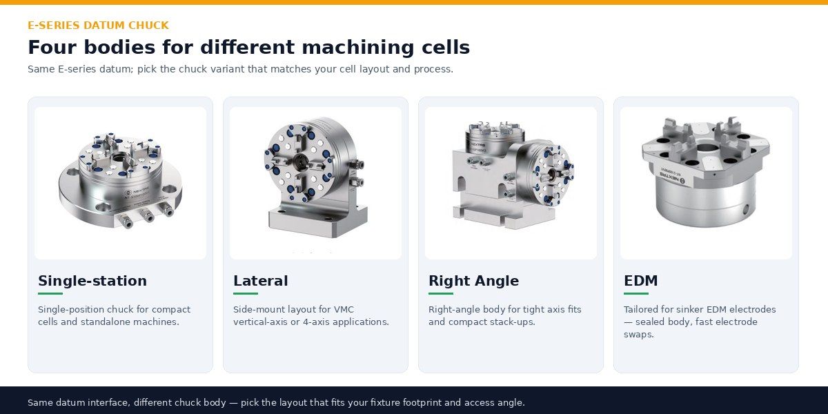
Four E-Series chuck bodies for different cells

The catalogue lists single-station, lateral, right-angle, and EDM body variants. Before PO release, verify the exact model, holder and spigot geometry, mounting, load and orientation, circuit, ports, options, and approved drawing; the family name alone does not prove a shared interface.

Catalogue view of four E-Series chuck body layouts; verify each selected model and interface drawing

Pneumatics, Setup & Maintenance for Unattended EDM

Published <0.003 mm repeat positioning accuracy is model-specific component data. Installed repeatability depends on the selected chuck, holder and spigot, mounting stack, load, environment, cleaning, temperature, circuit, and measurement method; define project-specific FAT/SAT acceptance before production.

Recommended air supply

  • The four listed models publish 0.5–0.8 MPa; confirm pressure at the chuck and the selected circuit.
  • Specify filtration, drying, drainage, hose, valve, and dielectric protection from the approved drawing, manual, and site conditions.
  • Record pressure, leakage, and response during the agreed commissioning test.

Setup & verification

  • Use the approved adapter, bolt pattern, dowels, torque, and flatness method for the selected model.
  • Cycle, load, and measure the installed stack using the agreed FAT/SAT sample size and traceable method.
  • Qualify a master holder or gauge at every station and record the cross-station results.

Maintenance & reliability

  • Define inspection and cleaning intervals from the actual dielectric, graphite, chip, cycle, sealing, and measured-condition data.
  • Where the selected model includes air blast, combine it with visual inspection and manual cleaning; do not rely on air alone.
  • Inspect seals, springs, holders, spigots, and ports to the approved manual and recorded condition; define spares at RFQ.

Robot-cell boundary: clamp, seating, and pressure signals may support process control, but they are not automatically safety-rated and cannot replace guarding, a validated safety-related control system, failure-state analysis, safe-state and recovery logic, complete-cell risk assessment, or FAT/SAT.

Acceptance & commissioning checks

Validation Checklist & Commissioning Plan

Use a project-specific purchase, FAT, and SAT plan to verify the selected model, holder and spigot, mounting, loads, environment, circuit, fault states, repeatability method, and complete-cell acceptance criteria.

Incoming inspection & acceptance criteria

Repeatability at Z datum
How to verify
Use a traceable CMM, indicator, or agreed method with the qualified master; define sample size, load, temperature, sequence, and uncertainty in the FAT/SAT plan.
Typical target
Use <0.003 mm only as the selected-model catalogue comparison point; agree the installed FAT/SAT criterion, cycles, load, temperature, and measurement uncertainty.
Clamping state and air-loss response
How to verify
Test the selected model, load direction, circuit, monitored states, and defined faults against the approved drawing and risk assessment.
Typical target
Record the model-specific response and complete-cell safe state; air-loss holding alone is not a safety validation.
Interface seating cleanliness
How to verify
Inspect and wipe the contact face; where equipped, test the documented cleaning cycle and then verify seating independently.
Typical target
Recorded surface condition, seating evidence, and measured datum meet the agreed project-specific acceptance criteria.
Pneumatic response time
How to verify
Measure at the chuck across the selected 0.5–0.8 MPa range and agreed circuit conditions.
Typical target
Recorded clamp and release timing meets the agreed project limit across the defined pressure, load, temperature, and fault cases.
Leak & seal health
How to verify
Use the approved leak-test method, pressure, hold time, medium, and acceptance threshold.
Typical target
Meets the agreed project-specific decay, leakage, and response criteria.
ITS compatibility
How to verify
Test the exact approved holder, pallet, adaptive spigot, revision, orientation, load, and machine-side drawing for every station.
Typical target
Exact geometry, seating, load, stack height, and measured datum meet the approved drawing and acceptance plan.
Documentation
How to verify
Request verification report + maintenance notes
Typical target
Traceable QC records for your quality system

Troubleshooting quick table

Z shifts after several cycles
Likely cause
Possible interface contamination, mounting, temperature, holder/spigot, circuit, load, or measurement change.
Fix
Stop and inspect the complete stack; compare cleaning, mounting, temperature, load, circuit, and measurement logs against the agreed control plan.
Holder won’t seat fully
Likely cause
Possible contamination, damaged or mismatched holder/spigot geometry, mounting error, or incomplete release.
Fix
Stop the cycle; inspect and verify the approved holder, spigot, interface, release state, and acceptance method before reuse.
Slow or incomplete release
Likely cause
Possible pressure-at-chuck, leakage, restriction, contamination, valve/hose sizing, or selected-circuit fault.
Fix
Restore the selected 0.5–0.8 MPa circuit condition, inspect filtration and drainage, and verify hose and valve sizing against the approved drawing.
Robot or handler motion is not safely inhibited
Likely cause
The complete-cell safety function, diagnostics, fault response, or reset/recovery logic is missing or unvalidated.
Fix
Stop commissioning and have the integrator validate guarding, safety-related controls, failure states, safe state, reset, recovery, and FAT/SAT; an ordinary sensor alone is insufficient.
Rust/contamination risk
Likely cause
Incompatible environment protection
Fix
Verify material, seals, ports, routing, shielding, dielectric compatibility, and maintenance for the selected model and environment.

Include in the RFQ: exact machine and station drawings, holder and pallet standard, selected spigot, mounting stack, loads and orientation, EDM/coolant environment, circuit and ports, expected cycles, sensing and control scope, risk-assessment boundary, and proposed FAT/SAT acceptance method.

Frequently Asked Questions

What repeat positioning accuracy is listed for the E-Series Model 100 variants?

Catalog data lists <0.003 mm repeat positioning accuracy for NT-S100P100V1, NT-S100P100V2, NT-S100P100V3, and NT-S100P80V1. This is model data, not a complete-process guarantee; verify the selected chuck, holder and spigot, mounting stack, environment, load, measurement method, and installed process during FAT/SAT.

How does the clamping mechanism work, and what force is listed?

The four listed models use pneumatic release with mechanical self-locking clamping. Catalog-listed force is >6,000 N for NT-S100P100V1, NT-S100P100V2, and NT-S100P100V3, while NT-S100P80V1 lists 4,000 N and a 15 kg clamping load. The 15 kg value is not a blanket workpiece load, robot payload, dynamic load, or machining-load rating. Confirm the selected drawing, load direction, pneumatic circuit, and air-loss behavior; loss of air alone does not prove that a machine or robot cell is safe.

Is it intended for ITS 50 / ER-036345-style holders and pallets?

The page identifies an ITS 50 / ER-036345-style application route, not blanket interchangeability. Before order release, confirm the exact holder and adaptive-spigot geometry, mounting pattern, orientation, stack height, load, and machine-side drawing for every station.

Which processes is it best suited for?

The E-Series is a candidate for die-sinking EDM, WEDM pallet transfer, electrode preparation, grinding, and inspection when the selected model, holder interface, environment, and validation plan fit the process. Suitability and results are application-specific.

How does it handle chips, dielectric fluid, and debris in automation?

Where the selected model and circuit include an air-blast or cleaning function, use it as one process-cleaning step and define wipe, purge, and inspection intervals for the actual dielectric, graphite, or chip load and sealing arrangement. Air blast does not by itself prove clean seating or installed repeatability.

What air supply quality is recommended for stable unattended cycles?

Published operating pressure is 0.5–0.8 MPa for the four listed models. Confirm the selected drawing and circuit, then specify air quality, filtration, drying, drainage, hose and valve sizing, and maintenance for the site; do not treat a generic filter grade or line length as a universal requirement.

How do I maintain the same Z reference across multiple machines?

Use verified holders and spigots plus a traceable master holder or gauge at each station. Establish the datum and measurement method, then record periodic results for every machine; a shared holder style alone does not guarantee the same installed Z reference or eliminate requalification.

Can it be integrated with robots or pallet systems safely?

Integration is possible only after the selected chuck, holder, payload, orientation, pneumatic circuit, sensing, control logic, guarding, and failure states are validated as a complete cell. Clamp, seating, and pressure signals may support process control, but they are not automatically safety-rated and do not replace the cell risk assessment, safety-related control system, FAT/SAT, or acceptance criteria.

Resources & Downloads

Fast quote

Request an E-Series EDM Chuck Quote

Three fields are enough — our engineers reply after reviewing the request with pricing and configuration advice.