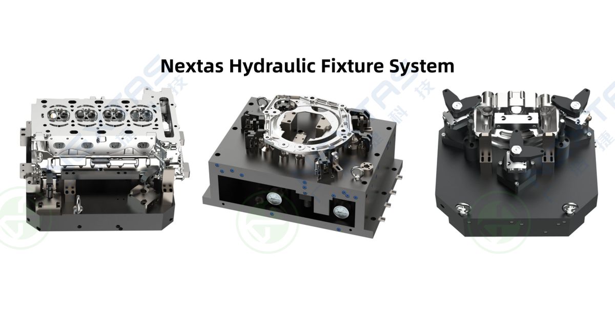
Study a custom hydraulic fixture when the same automotive part family runs often and manual loading causes a clear process problem. The problem may be slow clamp work, uneven force, poor support, hard access or a future automation handoff.
Do not start with a clamp-force target. Start with the part drawing, the surfaces that matter, and the way cutting force moves through the part. The fixture must locate the part, support it and hold it without creating a new form error.
Good fit
A stable part family, repeat demand, known machine access and a clamp sequence that can be tested.
Poor fit
An early prototype, a changing casting, unknown critical features or a job where simple modular workholding already meets the need.
When is the extra fixture complexity worth it?
Hydraulic workholding adds cylinders, seals, hoses, valves, a power unit and service work. That added system can be justified when it solves a measured loss. Record the current clamp time, operator work, rework, stoppages and changeover steps before asking for a return figure.
Low volume alone does not rule it out, and high volume alone does not approve it. A heavy or thin-wall part may need planned support even at modest volume. A simple part may still be better on a vise or modular plate at high volume.
Use a custom hydraulic fixture when the drawing and process show that controlled location, support and clamp order add real value. Use manual, pneumatic or modular workholding when it meets the same need with less risk and service work.
The clamp map starts with the drawing
Mark the main location points first. Then mark each feature that must stay within tolerance. These are often called critical-to-quality features, or CTQs. In plain terms, they are the dimensions and surfaces that the buyer will inspect.
- Locate: show which faces, holes or bosses set the part position.
- Support: place support near the cutting load without blocking tools or chips.
- Clamp: direct force into the support instead of bending a thin wall.
- Release: confirm the part can be loaded and removed without a trapped clamp.
- Inspect: define where and how the result will be checked.
Cast parts need extra care. Stock, draft and flash can vary. A hard stop that works on one casting may lift another. The fixture review should state which surfaces arrive as-cast, which are machined first and which support can move to follow the part.

Three reference layouts for stable part families
The examples below are planning routes, not named customer results.
Which clamp method fits the process?
| Route | Use it when | Check before release |
|---|---|---|
| Manual or modular | The part is simple, changes often or does not need a powered sequence. | Operator reach, torque method, support and setup variation |
| Pneumatic | Fast motion and a simpler air system can provide the needed force and control. | Air quality, force margin, pressure loss and state feedback |
| Hydraulic | The part needs a planned multi-clamp sequence, higher force range or compact powered clamps. | Circuit, force at the part, leak response, service access and heat |
| Zero-point base plus top fixture | The top fixture must move between machines or be set up offline. | Receiver layout, fixture load, stack height and transfer acceptance |
The current product page lists typical positioning repeatability down to 0.005 mm or less, application-related clamping force from 5 to 200 kN, and working pressure from 10 to 70 MPa. Those ranges describe the published product offer. They are not a promise for an unseen automotive part.

Circuit, machine and automation must work as one
The fixture, hydraulic power unit and machine controls form one working system. Agree the clamp order, pressure range, hold method, release order and response to pressure loss. State which sensors show a normal process state.
A pressure switch or clamp signal can help block the next machining step. It is not automatically a safety function. Guarding, safe stop, access control and other safety needs must be set by the full machine or cell risk review.
For robot loading, also define part-present proof, gripper release, clear positions, door control and who may reset a fault. Test the real part and payload. Do not approve the cell from a sensor list alone.
What the release test must prove
Plan the checks before the final build. The exact test depends on the part and plant, but the following set gives a useful start.
- Clean and reload the part several times, then inspect the chosen features.
- Check clamp order, support contact and force on the actual part range.
- Hold pressure and inspect for leaks using the agreed time and limit.
- Run a trial cut and compare the result with the unclamped part where form change matters.
- Create faults such as low pressure or a missing part in a controlled test.
- Confirm the reset and restart steps with operators and maintenance staff.
Maintenance frequency should follow the selected parts, fluid, duty, environment and maker instructions. A fixed daily, quarterly or yearly schedule cannot be set from a general web article.
ROI needs site data, not a fixed payback claim
Use the current process as the base. Record manual clamp time, cycles per shift, labour time, rework, lost production and fixture service cost. Then add the new fixture, power unit, machine work, controls, training, spares and maintenance.
Keep each assumption visible. If cycle demand changes, run the model again. This gives management a range it can challenge instead of a promised payback with no source.
What belongs in the quote packet?
Send the part model and drawing, material, casting state, location plan, critical features, machine and pallet data, cutting access, clamp-time goal and automation plan. Add the expected part range and any known form-change issue.
Ask the reply to separate the proposed layout, open risks, published component data, project-specific targets and planned acceptance tests. That split is more useful than a broad claim that hydraulic workholding is always faster or more accurate.
Reviewing a stable automotive part family?
Scope the part-family fixture
Send the drawing, datum plan, machine, load path and acceptance needs. Use the response to compare the proposed layout, open risks and release evidence.
Frequently Asked Questions
When should an automotive process not use a hydraulic fixture?
Avoid added hydraulic complexity when a changing prototype, simple part or proven modular setup already meets the need. Start with the process loss and part risk, not production volume alone.
What data is needed for a hydraulic fixture quote?
Send the part model and drawing, material and casting state, location plan, critical features, machine and pallet data, cutting access, expected part range, clamp-time goal and automation plan.
How should clamp force be set for a thin-wall part?
Set it from the support and load path, then test the actual part range. More pressure can bend a weak section. The release plan should include a form and feature check after clamping and cutting.
Can one hydraulic fixture serve several part models?
It may serve a controlled part family when the shared base, locators, supports, clamps and change parts are designed for each variant. Every variant still needs clearance, force and acceptance checks.
Do clamp and pressure sensors make a robot-loaded fixture safe?
No. They can show normal process states and help block machining. The complete cell still needs a risk review, guarding, safety functions, fault tests and controlled reset rules.
How often should a hydraulic fixture be maintained?
Set the interval from the selected seals, valves, fluid, duty, heat, contamination and maker instructions. Record leaks, pressure drift and wear, then adjust the plan from real service data.
Keep exploring
Related Articles
Continue with closely matched guides on custom fixture design, clamping strategy and production integration.
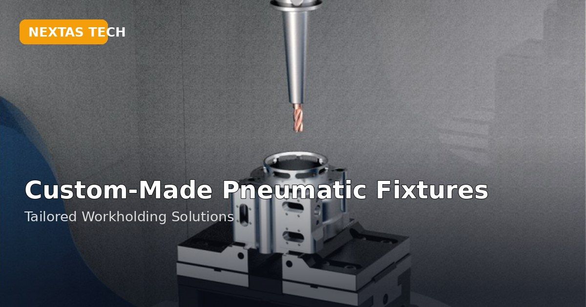
Custom Pneumatic Fixtures: RFQ Inputs and Acceptance Checks
Learn when a custom pneumatic fixture is justified, what a reviewable RFQ needs, and how to plan seating, pressure, trial-cut and recovery checks.
Read article →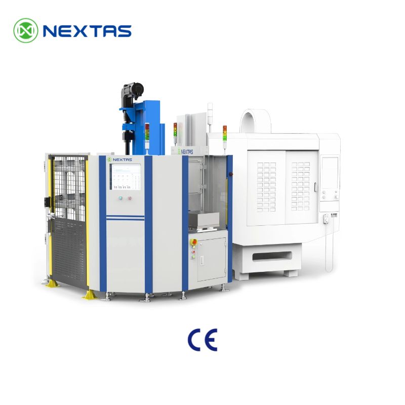
NEXTAS FMS Software: Scope, Interfaces and Acceptance
Review NEXTAS FMS software scope, machine, handling and data interfaces, order evidence, FAT/SAT stages and acceptance inputs before purchase.
Read article →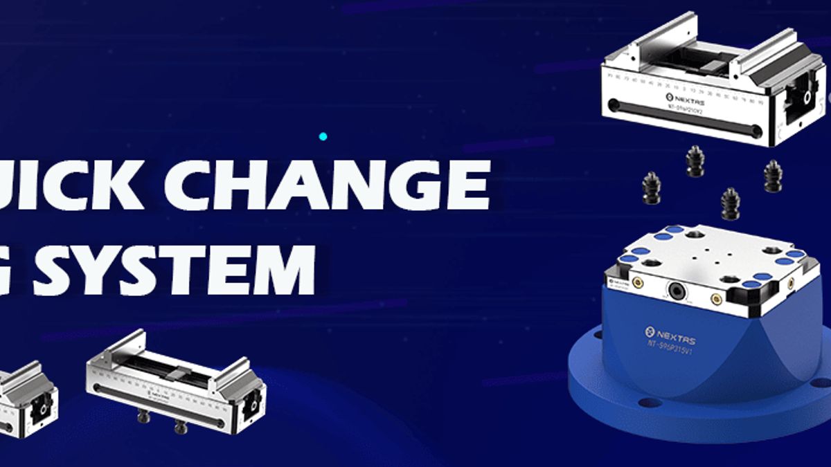
Robot-Loaded CNC Workholding: Vise and Zero-Point Integration
Plan the physical handoff between a robot, gripper, part, vise and zero-point receiver. Define signals, recovery steps and acceptance proof.
Read article →Match the hardware
Related Products
These product pages are the most direct next step if you are matching custom workholding hardware to a specific part family or process.
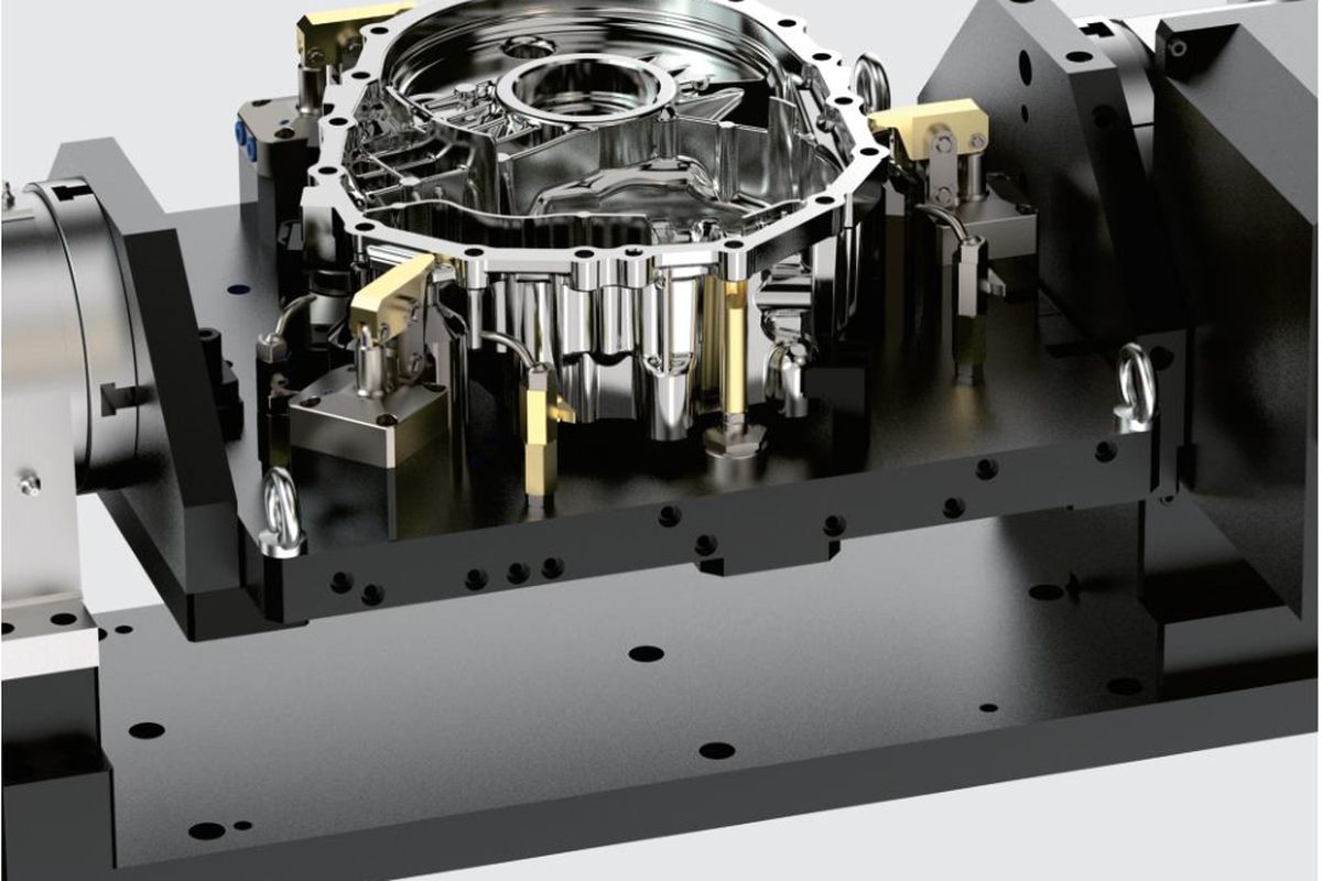
Custom Hydraulic Fixture Systems for CNC Machining
Custom hydraulic fixture systems for CNC machining with stable clamping force, repeatable locating and clean integration for robotic loading, pallets an...
View product →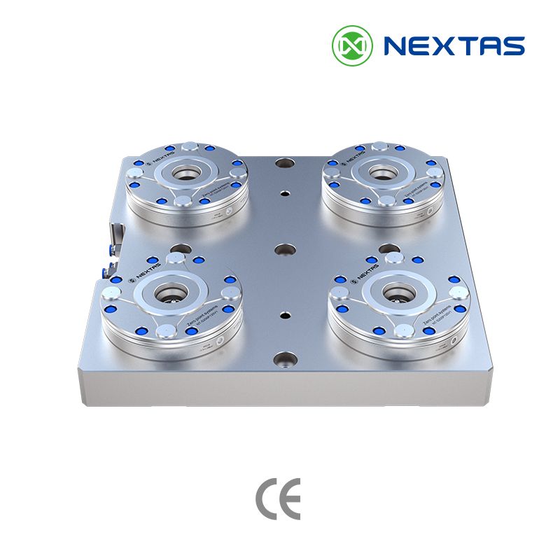
Zero-Point Clamping Systems
MFG zero-point systems for CNC automation, pallets and fixtures, with tapered positioning, mechanical self-locking and repeatability up to ≤0.003 mm.
View product →CNC Automation Systems for Pallet Loading, Rotary Storage & FMS Cells
CNC automation systems for pallet loading, rotary storage, truss handling and FMS-ready machining cells. Match the right layout by machine count, pallet...
View product →Need a fixture review for your part?
Send your drawing, datum strategy, and clamping constraints. Our team can review whether a custom pneumatic or hydraulic fixture is the right approach and what inputs matter most.
Request Fixture Engineering Review →