Goal / operation
Aggressive roughing, high torque
Recommended jaw & grip method
Serrated jaws + longer grip length
Why it works (notes)
Serrations bite into scale; longer engagement improves stability on 5-axis tool access.
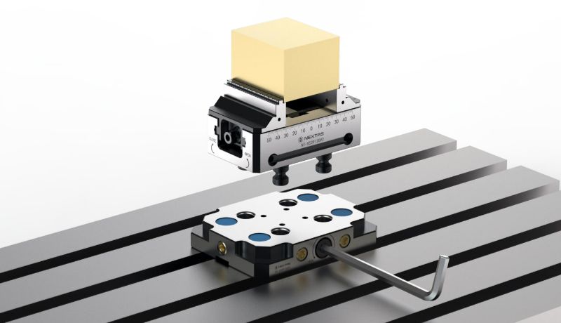
Watch the self-centering vise in action
See how the vise supports centered holding, 5-axis tool access, and fast setup carryover between machines or pallets.
This series is built for shops that need centered holding, cleaner tool access, and predictable setup repeatability across mixed part sizes. Ideal when the vise needs to move between zero-point plates, pallets, or automated loading workflows.
Compared with the P75/P110/P150 pneumatic vise — chosen when the priority is raw clamp force and air/hydraulic actuation — this 5-axis self-centering vise is the lighter, lower-profile option built around 52/96 mm zero-point spigots, tool-side clearance, and quick carry between machines.
Best fit
A strong choice for aerospace, mold, and mixed-batch parts where centered grip, tool clearance, and repeat setup carryover all matter.
Compare first
Those three decisions usually resolve whether the vise fits the real part family before you dive into the full specification tables.
Go next
Selection sizes the vise. Integration ties it into zero-point or pallets. Specs & Downloads is where the dimensioned drawings live.
We recommend the right self-centering vise platform, jaw strategy, and zero-point mounting path before you spend time comparing model tables.
Fast RFQ paths
Share your part family and target clamping range so engineering can reply with the right platform.
The RFQ form will prefill Self-Centering CNC Vise for a faster reply.
Send part length, width, height, material, rough or finished surfaces, and whether the part needs five-side access.
Tell us if you prefer 52 mm or 96 mm mounting, soft jaws, serrated jaws, quick-change jaws, or zero-point mounting.
Include target quantity, delivery region, required repeatability, and whether you need drawings, STEP files, or a paired setup.
Learn how the engineering works behind our Self-Centering Vise.
| Family | Spigot Distance | Repeat Positioning Accuracy | Clamping Force | Maximum Torque | Material | Representative Models |
|---|---|---|---|---|---|---|
| 52 Self Centering Vise | 52 mm | <0.02 mm | 14,000 N | 70 Nm | Hardened stainless steel | NT-S52P105V2 / 130V2 / 170V2 / 210V2 |
| 96 Self Centering Vise | 96 mm | <0.02 mm | 20,000 N | 100 Nm | Hardened stainless steel | NT-S96P160V2 / 210V2 / 260V2 / 310V2 / 360V2 |
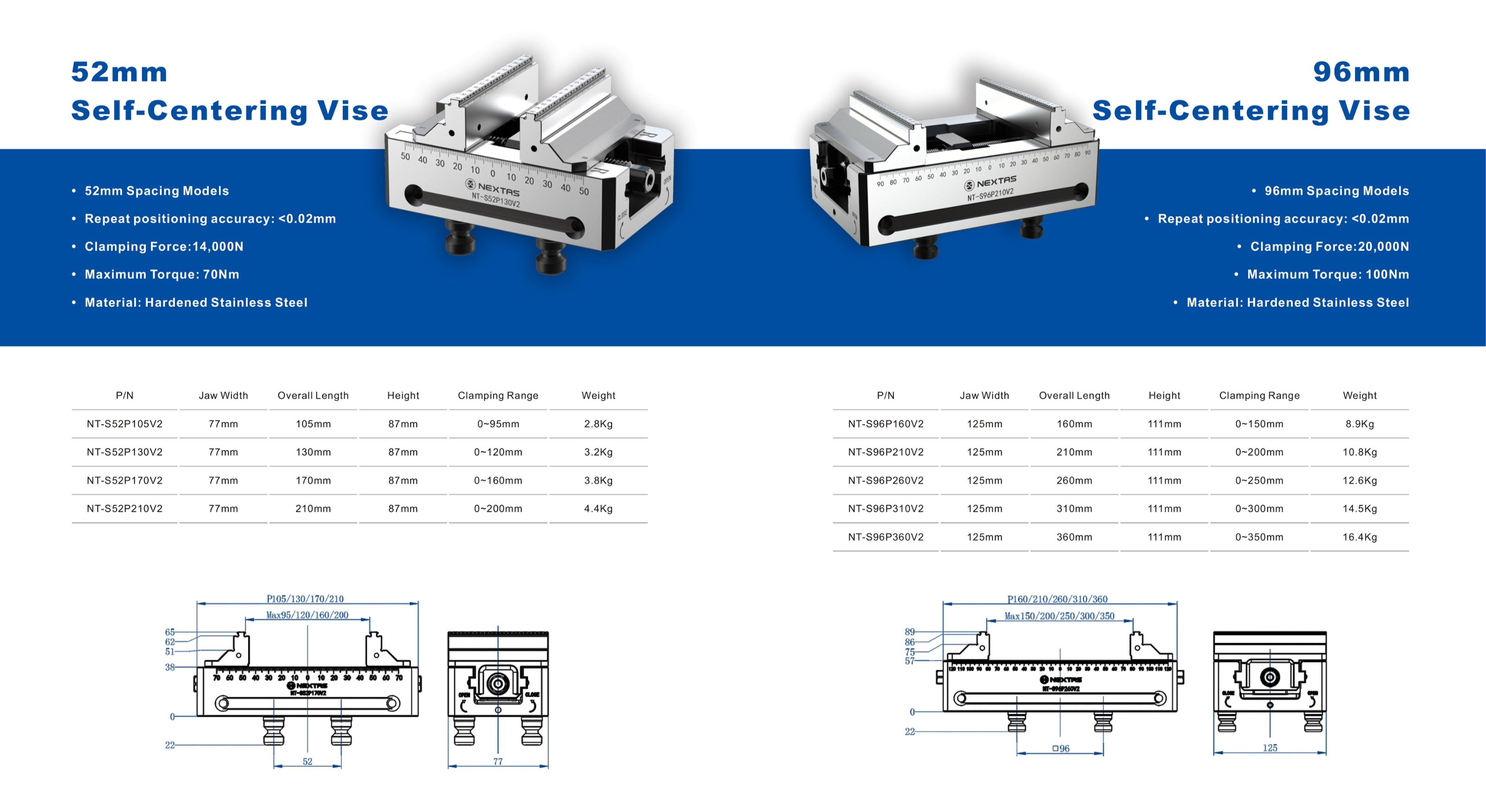
The table below matches the 52 mm and 96 mm self-centering vise families shown in the catalogue, so buyers can compare footprint, clamping range, and shipping weight without switching back to the PDF.
| Product Code | Jaw Width | Overall Length | Height | Clamping Range | Weight |
|---|---|---|---|---|---|
| NT-S52P105V2 | 77 mm | 105 mm | 87 mm | 0 ~ 95 mm | 2.8 kg |
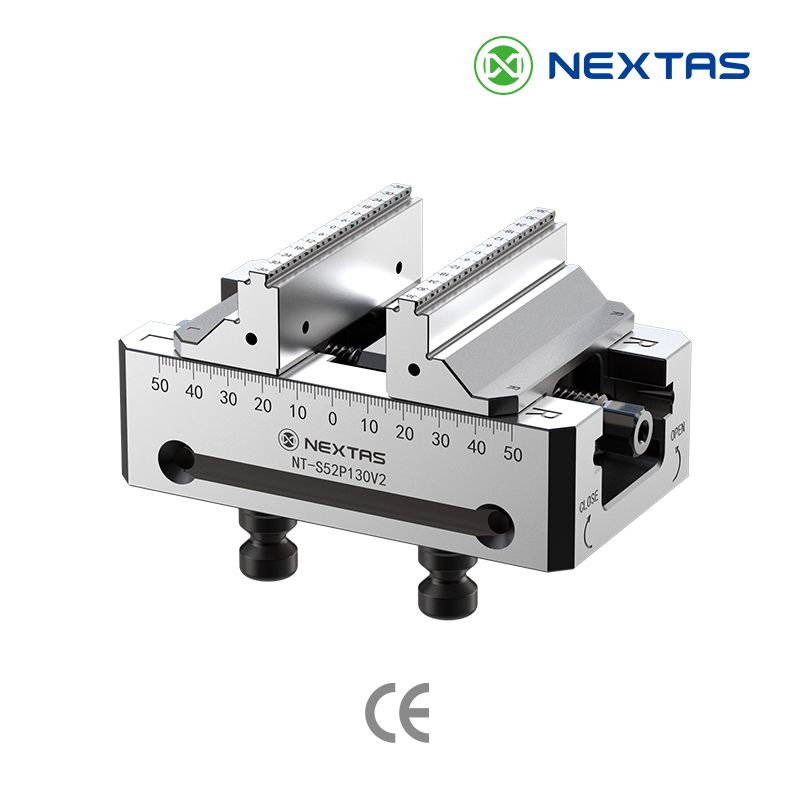
| NT-S52P130V2 | 77 mm | 130 mm | 87 mm | 0 ~ 120 mm | 3.2 kg |
| NT-S52P170V2 | 77 mm | 170 mm | 87 mm | 0 ~ 160 mm | 3.8 kg |
| NT-S52P210V2 | 77 mm | 210 mm | 87 mm | 0 ~ 200 mm | 4.4 kg |
| NT-S96P160V2 | 125 mm | 160 mm | 111 mm | 0 ~ 150 mm | 8.9 kg |
| NT-S96P210V2 | 125 mm | 210 mm | 111 mm | 0 ~ 200 mm | 10.8 kg |
| NT-S96P260V2 | 125 mm | 260 mm | 111 mm | 0 ~ 250 mm | 12.6 kg |
| NT-S96P310V2 | 125 mm | 310 mm | 111 mm | 0 ~ 300 mm | 14.5 kg |
| NT-S96P360V2 | 125 mm | 360 mm | 111 mm | 0 ~ 350 mm | 16.4 kg |
Match jaw style to material, surface condition, and cutting load. The matrix below is a practical starting point for selecting jaws on a 5-axis self-centering vise (and for repeatable automation setups).
Repeatability is a system result (interface + vise + jaws + process). Use the checks below to stay on track when you’re chasing tight tolerances on 5-axis workholding.
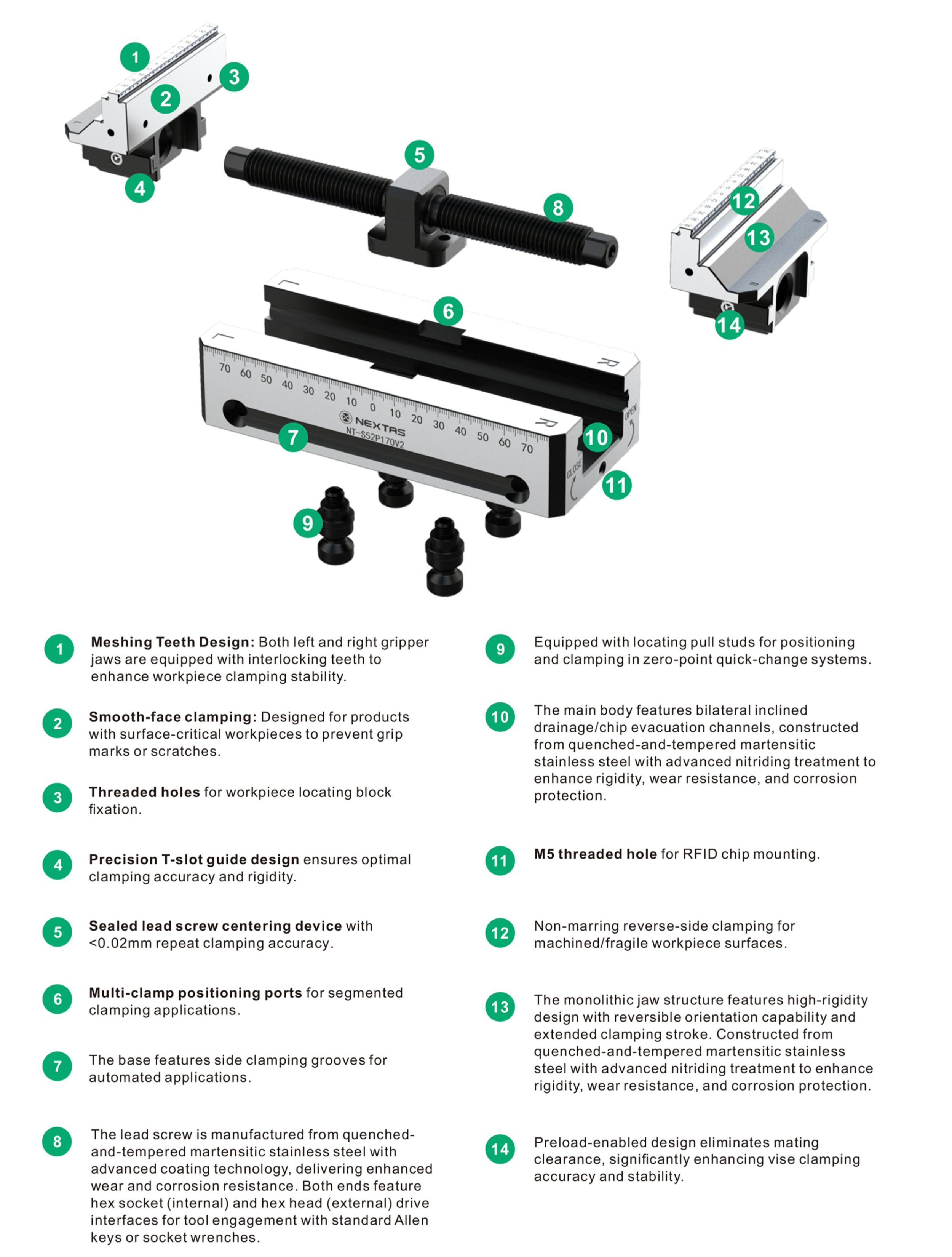
Built from hardened tool steel (HRC 50-55) with a backlash-compensated lead screw, the self-centering mechanism applies equal force to both jaws regardless of workpiece shape. This ensures the workpiece centers on the spindle axis, delivering <0.02 mm repeat positioning accuracy for parts requiring symmetrical multi-face machining.
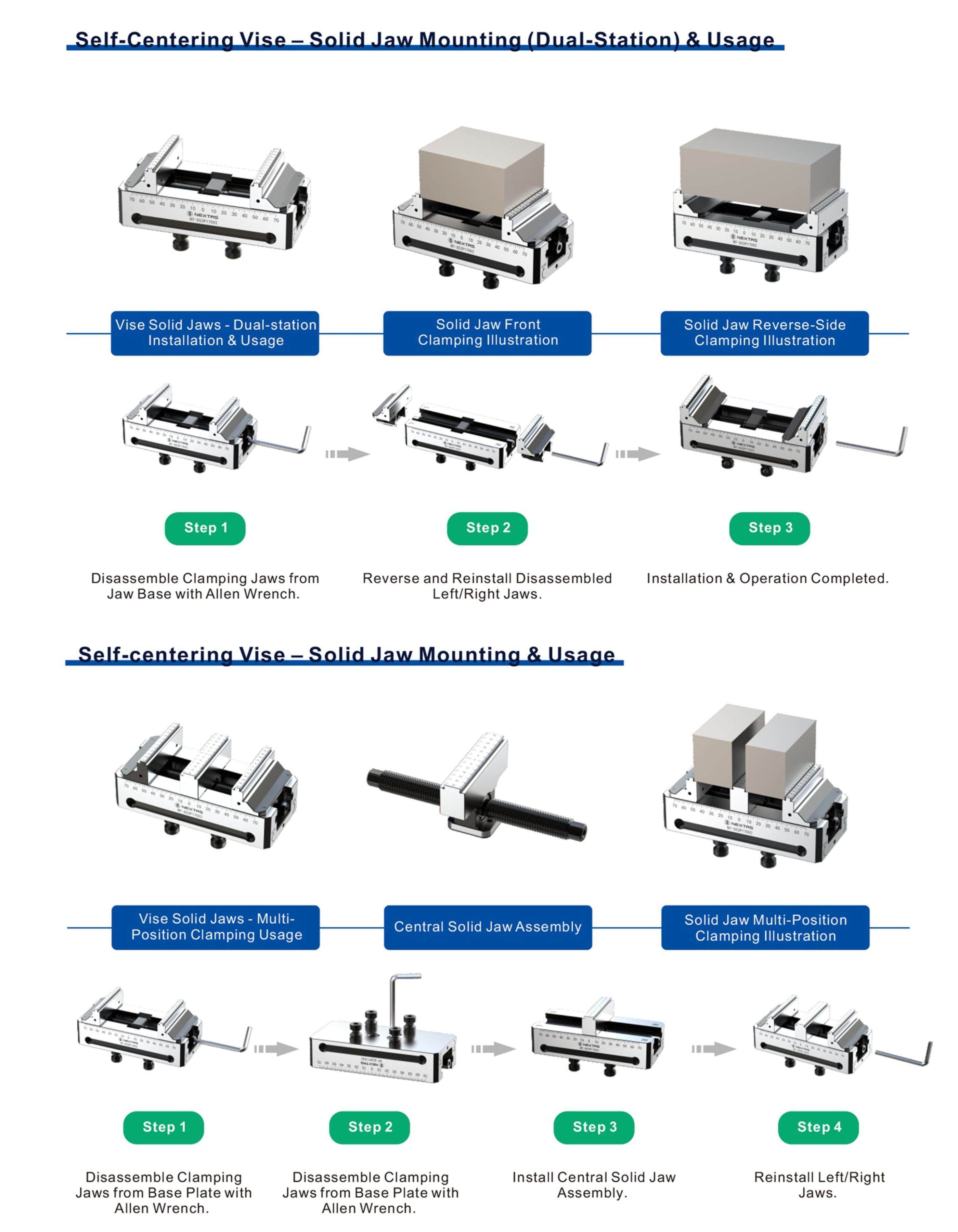
The vise takes standard and custom jaws, so you can clamp anything from raw castings to finished parts. The quick-change jaw design lets you reconfigure a setup in minutes instead of stripping the vise down.
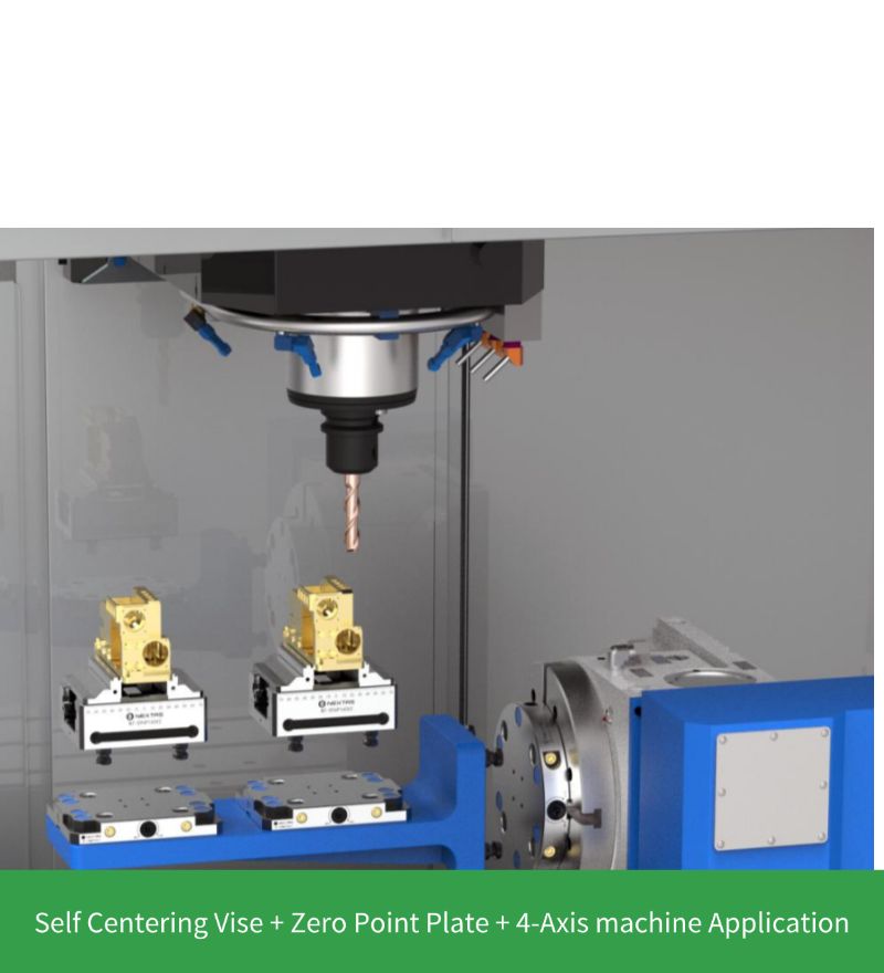
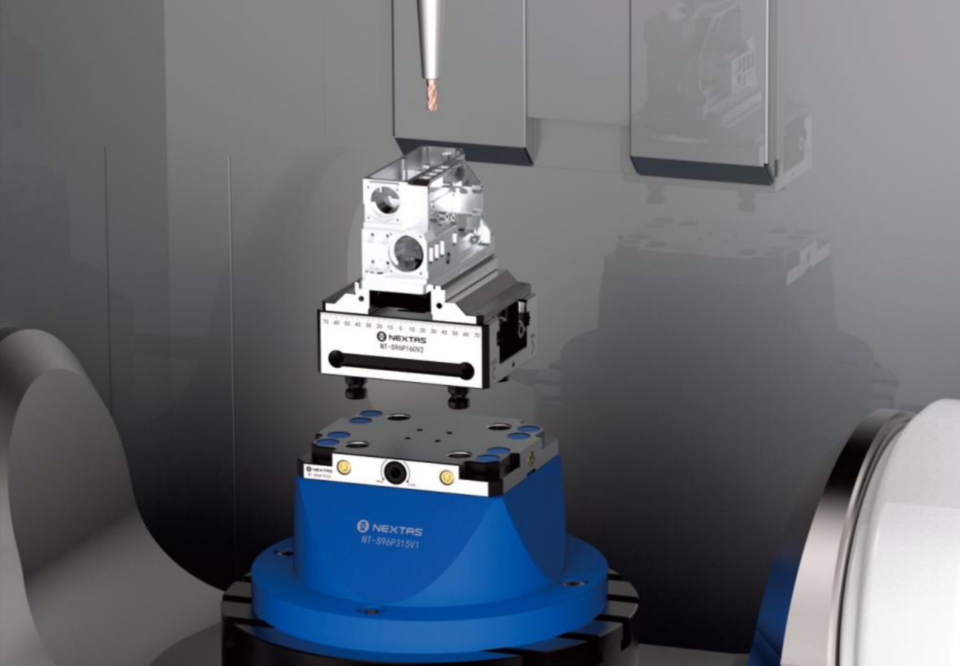
The vise base mounts straight onto our zero-point clamping systems for fast, precise setup. Once bolted down it behaves as one rigid unit with the table, which keeps chatter down during high-speed, high-feed cutting and protects surface finish.
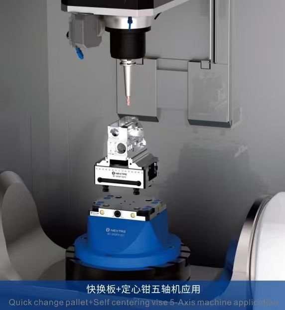
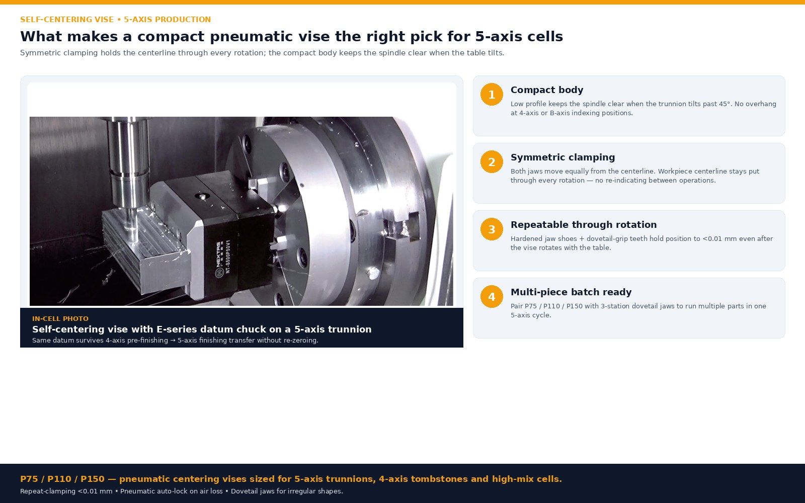
The low-profile body keeps the cutter clear of the fixture when the table tilts, so you can run shorter tools — less vibration, better cutting in tight 5-axis work.
Dimensional drawings, jaw-travel ranges, and mounting interfaces for 52 mm and 96 mm vise models.
5-AXIS PRODUCTION
Symmetric clamping holds the centerline through every rotation; the compact body keeps the spindle clear when the table tilts.
See our vise in action across various industries and setups.
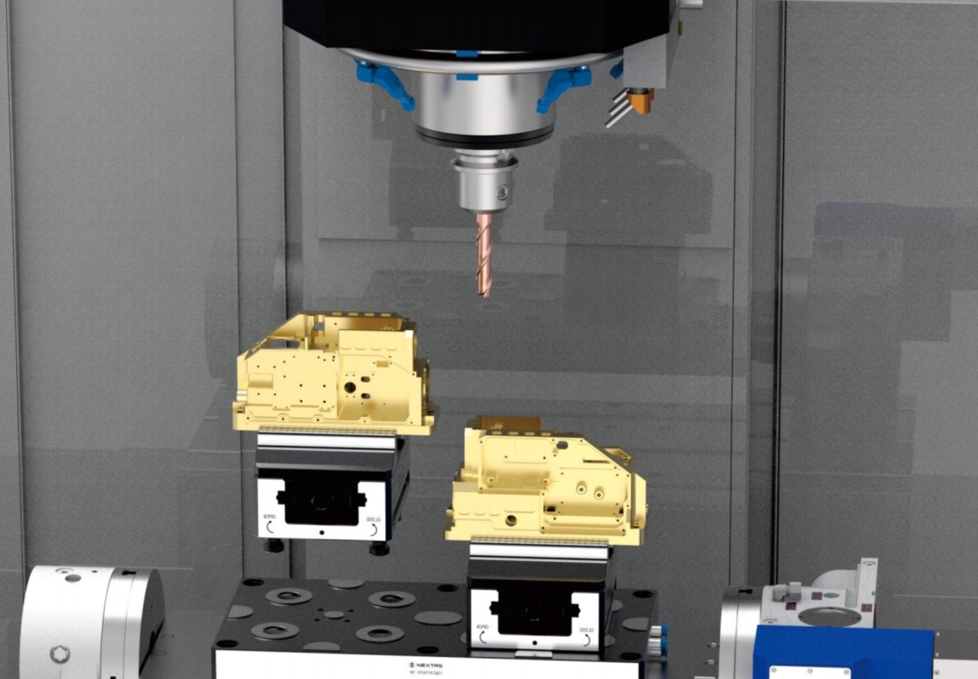
The compact design of the NEXTAS self-centering vise provides excellent tool accessibility for 5-axis machining. For impellers, molds, or complex structural parts, it keeps tools clear and lets you machine complex surfaces with tight tolerances.
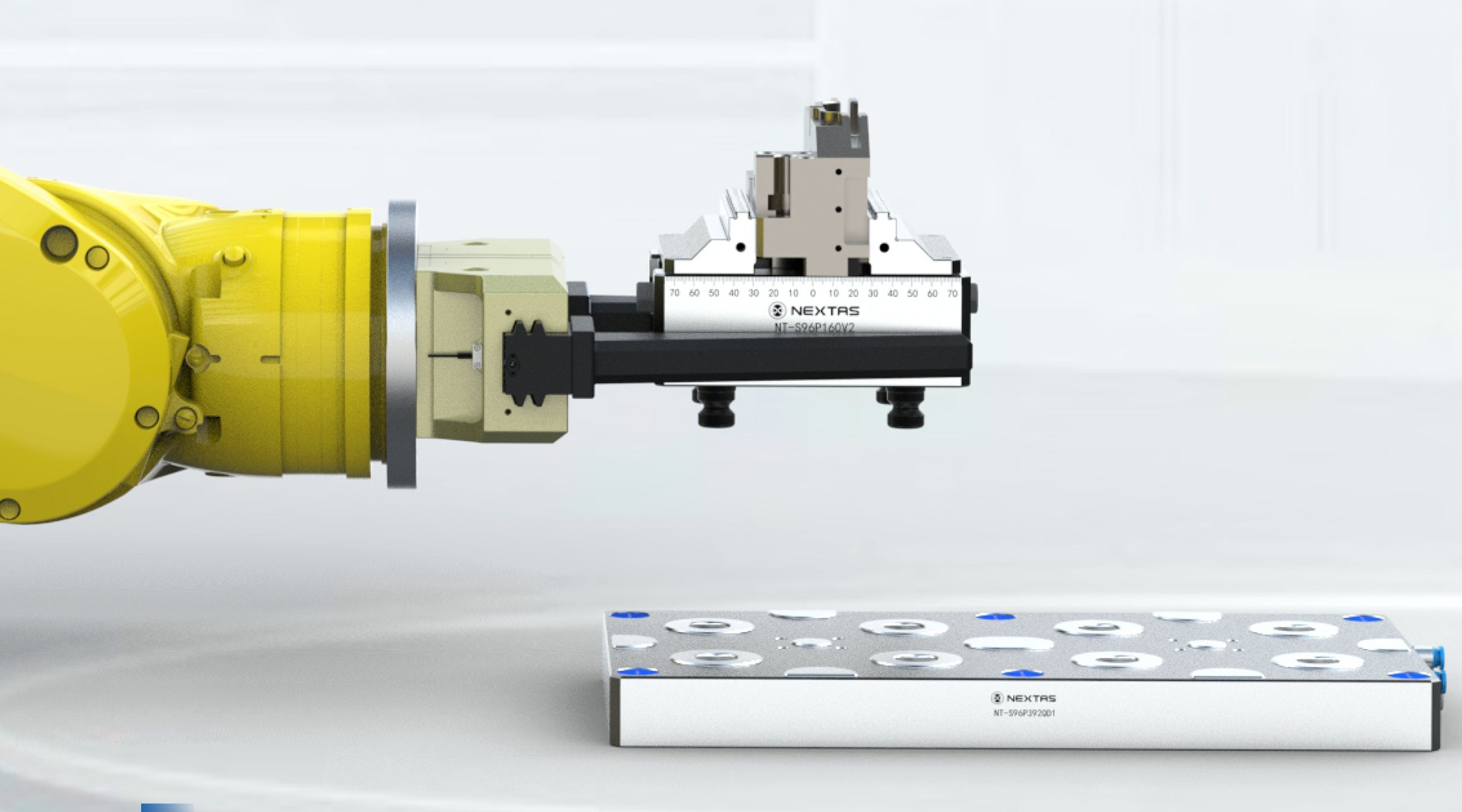
The gripping interface on the side of the vise allows for straightforward integration with robotic arms, enabling automated workpiece loading and unloading for a 24/7 unmanned production line.
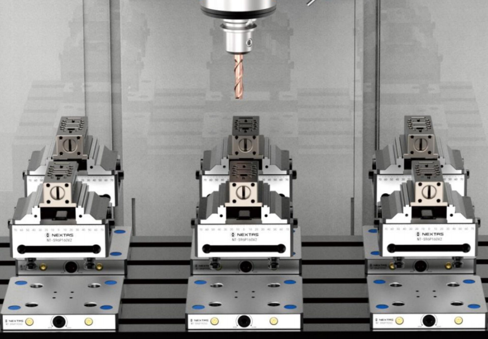
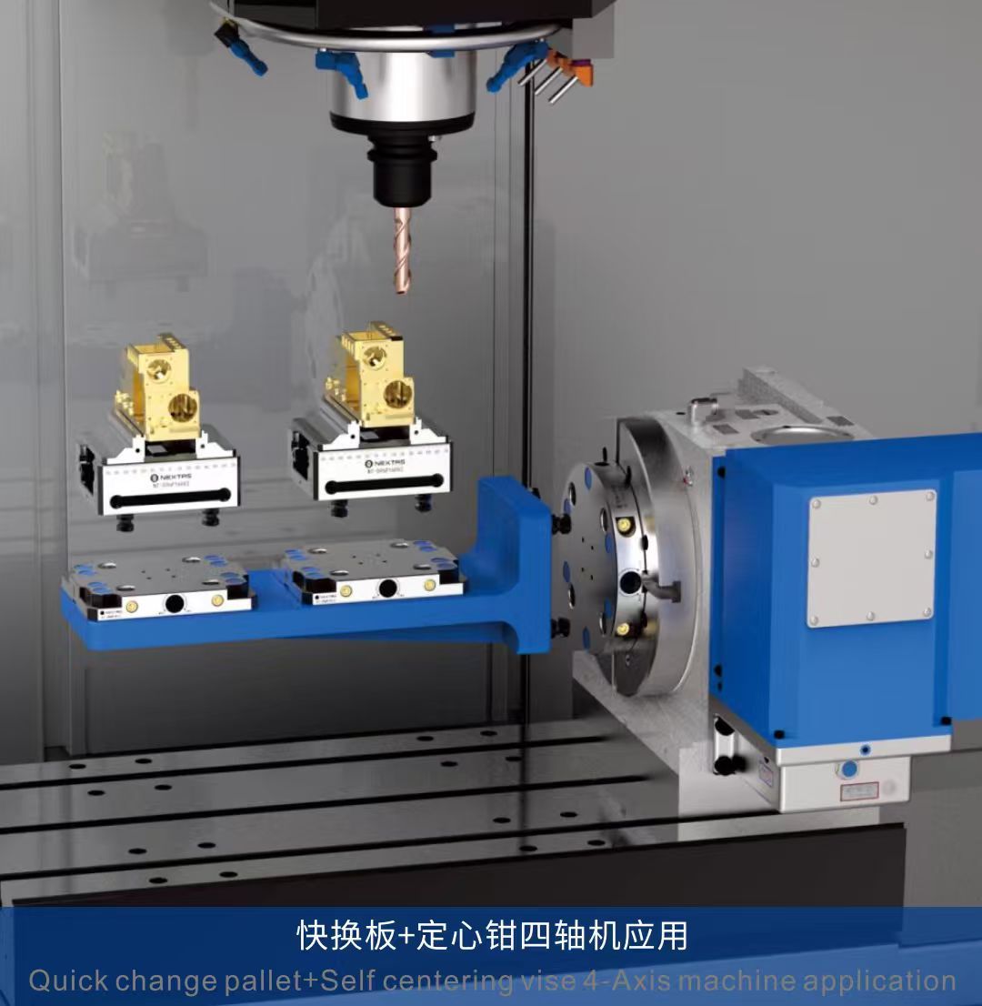
Arranging multiple vises on the machining center's worktable allows for the processing of multiple workpieces in a single setup, significantly boosting production efficiency.
Mounting the vise on a standardized pallet allows for offline pre-setup, sharply cutting machine downtime and increasing equipment utilization.
By using special jaws, it can securely clamp various irregularly shaped workpieces such as castings and forgings, providing a stable machining base.
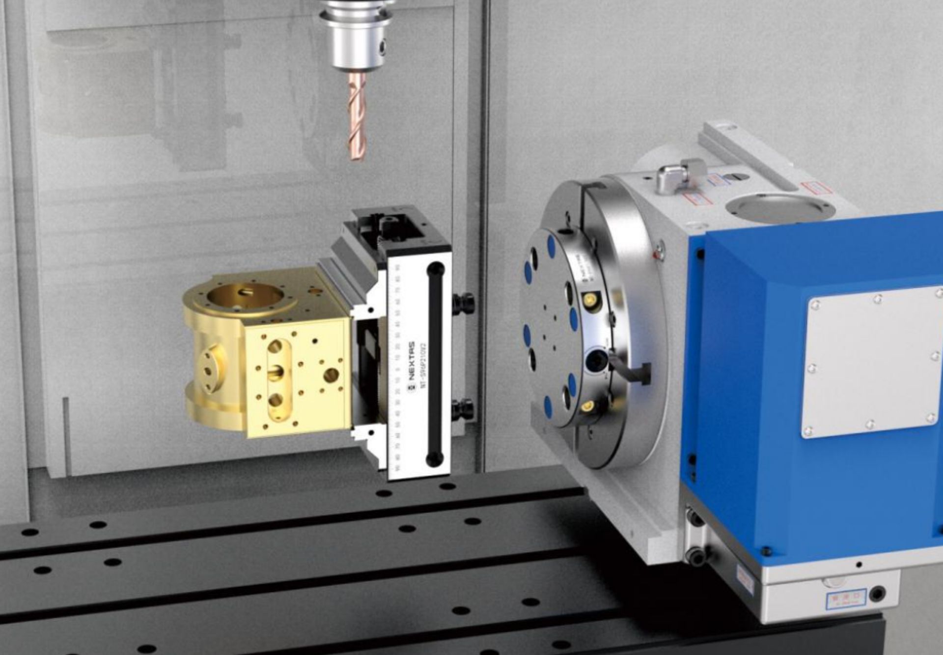
The vise's lightweight and high-rigidity features also make it suitable for mounting on a 4th-axis rotary table for multi-sided component machining.

Paired with V-jaws, it can easily achieve precise and stable center clamping of round bar workpieces, suitable for machining shaft-like parts.
Self-centering vises in aerospace, medical, and automotive prototype cells — from 5-axis aluminum parts to hardened steel inserts.


Engineers care about repeatability. Procurement cares about verification. This section gives both teams what they need.
Built for mixed part families and frequent setup changes. The modular design takes special jaws and quick-change jaws, so you can switch from castings and forgings to finished parts without wasting spindle time.
Need more than a standard vise? We support customization and provide one-to-one technical service. For complex projects, we can help with fixture solution planning, process planning, and application guidance.
We maintain a verified supplier presence on Made-in-China. This gives procurement teams an extra layer of confidence for supplier due diligence and compliance review.
A short demo helps your team confirm size, handling, and typical applications before requesting CAD files or a quote.
Faster setup, cleaner datums, and more stable cutting—especially on 5-axis.
For repeatability, treat the vise like a fixture: mount it once, qualify it, and reuse the same reference every changeover.
Matching jaws to material and surface condition is the easiest way to prevent slip, distortion, and chatter.
A quick verification routine helps you protect tolerances while keeping cycle time low.
A short, repeatable routine helps a self-centering vise deliver stable results across pallets, shifts, and operators.
Wipe interface + jaw bed; remove burrs and chips
Tip for 5-axis / automation: Treat it like a fixture: cleanliness = repeatability
Seat on table/pallet/zero-point; apply specified tightening pattern
Tip for 5-axis / automation: If you use a zero-point system, avoid re-indicating every changeover
Probe/indicate vise centerline once; store as a work offset/macro
Tip for 5-axis / automation: Makes multi-pallet and robot loading predictable
Use consistent torque; confirm full jaw contact
Tip for 5-axis / automation: For thin walls: use soft jaws + support pads
Probe a reference feature (first-article)
Tip for 5-axis / automation: Log the offset; watch for drift after warm-up
For long cycles: re-check after jaw swaps or tool changes
Tip for 5-axis / automation: Small checks prevent big scrap batches
Simple care keeps the lead screw, jaw guidance, and contact surfaces performing like a precision workholding system.
If you machine complex parts (aerospace, medical, precision molds), this workflow keeps access high and collisions low.
Use serrated jaws + higher clamp force. Keep grip length conservative for stability.
Switch to soft jaws or precision pads. Probe critical features to protect tolerance stack-up.
A simple checklist for selecting model size, jaw set, and mounting interface—so you get predictable accuracy on day one.
Use your part envelope, cutting load, and changeover frequency to decide.
| Model | Best for | Notes |
|---|---|---|
| NT-S52P170V2 | Compact parts, 5-axis clearance, lighter rotary setups | Fast handling, lower mass, excellent for dense multi-vise layouts |
| NT-S52P210V2 | Larger parts, heavier cutting, more jaw travel | Higher clamping force and envelope for wider part families |
If you share a drawing + material + target tolerance, we can recommend jaw style and grip strategy.
More context for engineering teams evaluating 5-axis workholding and repeatable setups.
Mechanism overview, repeatability, and jaw strategy.
Tool access, fewer re-clamps, and collision risk reduction.
Setup carryover, pallet changeover, and repeatable datum across mixed-batch 5-sided machining.
Your questions, answered.
The vise uses a backlash-compensated leadscrew that drives both jaws to converge at the centerline with matched force, so the part's theoretical center stays aligned with the spindle regardless of the starting shape. For castings, forgings, or sawn stock, pair the centering mechanism with serrated jaws for positive grip on rough surfaces.
Daily: remove chips and coolant from the leadscrew and jaw slides. Weekly: apply high-pressure grease through the grease nipple on the leadscrew. Protect the precision ground surfaces from impact, and inspect jaw mating faces for wear at every tooling change. The HRC 50–55 tool-steel body handles production loads, but contamination — not wear — is the usual cause of accuracy drift.
Yes. The base carries a standardized 52 mm or 96 mm mounting pattern (model-dependent), so it drops directly onto NEXTAS zero-point plates and is compatible with other common zero-point brands. Changeover typically completes in under a minute with <0.005 mm repeatability on the mounting interface — the vise itself locks rigidly to the machine table through the zero-point receivers.
Three are relevant for automated cells: (1) standardized gripper grooves on the body allow a robot to load or unload the entire vise as a fixture; (2) hydraulic and pneumatic actuation modules are available for programmatic clamp / unclamp via PLC or M-code; (3) the 52 / 96 mm zero-point mounting pattern makes the vise a drop-in element of pallet-change and lights-out workflows.
The jaw mechanism includes a pull-down geometry: as clamping force rises, the jaws are drawn toward the base rather than being pushed upward. The workpiece seats flat against the jaw reference surfaces, which supports tight parallelism tolerances and consistent surface finish during high-feed cutting.
Both. Hobbyists benefit from the simple self-centering action and repeatable results. In production, the high clamping force, rigidity, and reliable accuracy make it a fit for CNC and 5-axis machining. Share your machine and workpiece envelope and we can recommend the right size and jaw type.
Yes. Jaw pads are serviceable wear parts and are swapped when the gripping surface is worn or when moving between jaw styles (smooth, serrated, or soft jaws). Standardizing the torque and datum on jaw changes keeps clamping consistent from setup to setup.
The common root causes are chips or coolant residue on the jaw faces, contamination on the leadscrew, or a jaw style mismatched to the workpiece surface. Corrective sequence: clean the jaw faces and vise bed, re-grease the leadscrew per the maintenance interval, and re-select the jaw style for the workpiece condition. If the behavior persists, the engineering team can review a photo of the part and jaws to confirm root cause.
Yes. The vise is engineered for CNC environments, including 5-axis setups. It supports repeatable positioning, rigid clamping, and common mounting paths such as direct base mount or integration with pallet / zero-point systems (model-dependent).
Catalog models are typically shipped in roughly 15–25 days after purchase-order confirmation. Custom jaw profiles, matched pairs, or soft-jaw pre-machining add 1–2 weeks. Committed lead time is confirmed in writing once the BOM and serial configuration are locked.
Every unit ships with a factory inspection report covering jaw parallelism, base flatness, and measured repeatability against the listed specification. Material certificates for the HRC 50–55 tool-steel body, calibration records, and the written warranty terms are available on request at order time.
Resources & Downloads
Request the full self-centering vise catalogue, share your machine and part data for file matching, and get the right sizing guidance before setup starts.
Get the catalogue pages covering model range, jaw options, clamping range, and typical 52 / 96 mm platform combinations.
Send your machine model, part envelope, material, and whether the vise will sit on a zero-point plate so our team can match the right STEP files faster.
Request CAD Files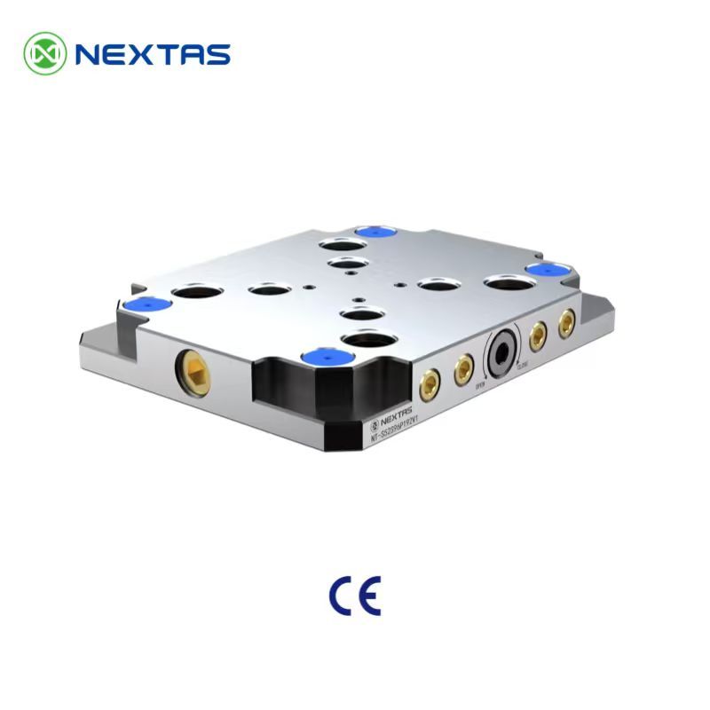
Build a repeatable base under the vise so setups move from machine to machine without re-indicating.
View Details →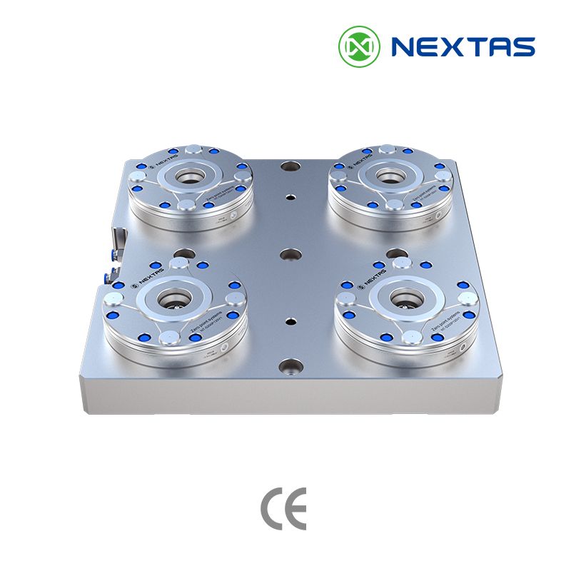
Move vises, pallets and fixtures faster with a receiver-side changeover system built for repeatability.
View Details →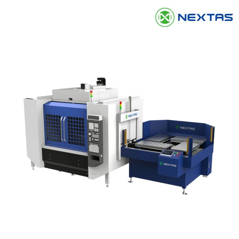
Pair pallet automation with self-centering vises when unattended loading and offline setup are part of the project.
View Details →Fast quote
Three fields are enough — our engineers reply within one business day with pricing and configuration advice.