A high-mix shop should standardize the interface, not just buy the same plate twice. The interface is the full set of parts that locate and hold the fixture: the machine plate, receiver, pull stud, bolt pattern, orientation and top tool. If one item changes without review, the shared standard may no longer be shared.
This approach works best when operators move the same vises, pallets or fixture tops between repeat jobs. It can reduce repeated alignment work and make offline setup easier. It does not remove the need to check each machine, fixture and process.
Plain answer
Use a manual zero-point plate when an operator will make the change and one fixed interface can serve several jobs. Do not call the system universal until the drawings, load path, stack height and clean-reload test all pass.
Which jobs should share the same plate interface?
List the work that you want to move first. A good first group has a stable part family, known cutting loads and top tools that already work well. A bad first group mixes unknown fixtures, weak base plates and parts that still move during cutting.
For each job, record the machine table, rotary or tombstone, the top fixture, and the finished part. Then mark the surface or point used as the location reference. Engineers often call this the datum. In plain terms, it is the known place from which the rest of the setup is measured.
| Check | Why it matters | Useful evidence |
|---|---|---|
| Available footprint | The plate and release tool must clear the table, rotary and guards. | Machine-table drawing and photos |
| Top-tool base | The vise or fixture needs enough material and the right bolt access for studs or an adapter. | Bottom-view drawing with hole depths |
| Stack height | Extra height changes tool reach, stiffness and machine travel. | Section view from table to part |
| Load path | Fixture mass alone does not describe cutting force, overhang or turning moment. | Part mass, centre of gravity and main cut direction |
| Transfer route | Moving between a CNC and an inspection machine adds another alignment step. | Station list and buyer-set transfer limit |

The 52 mm or 96 mm family decision
The current NEXTAS manual plate page lists 52 mm and 96 mm product families. The published values apply to those listed products, not to every plate or complete machining process.
Both listed families use manual release and hardened stainless construction. Manual release keeps the setup simple when an operator is present. It is not the right choice when the machine, pallet changer or robot must control release and confirm state.
Can the existing vise or fixture be adapted?
Sometimes, but the drawing must decide. Do not drill a stud pattern into a vise because there appears to be room. First check the base thickness, screw depth, internal parts, support area and access for the release tool.
- Use the existing base only when the maker or an engineering review confirms the new holes and loads are acceptable.
- Add an adapter plate when it protects the original tool, spreads the load or gives better bolt access.
- Choose another top tool when the adapter would create too much height, overhang or lost travel.
The word compatible should follow a passed drawing review. A shared pitch or nominal size is only the start. Stud geometry, receiver shape, fasteners and load limits must also match.

What every station must prove
Receiver repeat positioning is not the same as part accuracy. The complete result also depends on plate alignment, stud fit, fixture stiffness, part location, tool wear, temperature and inspection method.
Set a limit for each step before the trial. Start with one clean plate and one known fixture. Load, measure, unload, clean and reload it several times. Record the result rather than keeping only the best reading.
Next, repeat the check on every machine that will use the standard. If the carrier will also visit a coordinate measuring machine, check that station as its own setup. The receiver value alone cannot prove the shift between two different machines.
- Record the master plate alignment on each machine.
- Use the same cleaning and seating steps for every reload.
- Inspect studs, locating faces and fasteners for damage.
- Run a first-part check after a new top tool or adapter is added.
- Define who may accept a drift, reset an offset or stop the process.
When manual release no longer fits
Manual release is a good fit for operator-led setup and simple offline preparation. A pneumatic zero-point plate should be reviewed when release must come from the machine or cell, or when the process needs state feedback.
That change is an engineering project, not a direct upgrade promise. Air quality, pressure at the module, valves, signals, fault response, guarding and the safety plan all need review. A normal clamp signal does not prove a safety-rated function.
What belongs in the standardization map?
A useful review starts with the gaps. Send the machine-table or rotary drawing, each top-tool base drawing, the fixture and part mass, the main cut direction, available height, and the route between machines. State whether release will stay manual or may become automatic later.
Also state your own clean-reload and cross-station limits. NEXTAS can then review a plate family, possible adapters and missing evidence. Final fit and process results remain subject to the selected model, approved drawings and acceptance test.
Standardizing a high-mix shop?
Map the shared interface before you buy
Send the machine, top-tool and transfer drawings. The reply should separate confirmed fit, open checks and the acceptance test.
Frequently Asked Questions
Does universal mean any vise will fit the plate?
No. Universal describes a standardization goal, not automatic fit. Check the vise base, stud geometry, bolt pattern, support area, stack height and load before approval.
How do I choose between the 52 mm and 96 mm families?
Start with the selected model data, fixture footprint, cutting load, stack height and future machine list. Do not choose from nominal size alone. The approved drawing and acceptance test should confirm the final family.
Can I add pull studs to an existing vise?
Only after a drawing review. The base needs enough material, safe screw depth, clear internal space and a sound load path. An adapter plate may be safer when those points are not clear.
Does receiver repeatability prove accuracy between two machines?
No. It describes the receiver interface under stated conditions. Cross-machine transfer also includes plate alignment, fixture stiffness, part location, temperature and the inspection method.
When should a shop consider a pneumatic plate instead?
Review a pneumatic plate when release must be controlled by a machine, pallet changer or robot, or when state feedback is needed. Air supply, signals, faults, guarding and safety functions must then be checked as one cell.
Keep exploring
Related Articles
Continue with closely matched guides on zero-point selection, repeatability, plate layout and retrofit planning.

High-Performance Zero-Point Plates: When the Premium Is Worth It
Decide when a premium zero-point plate is justified by checking the selected model, load path, support count, stack height, mounting, and release tests.
Read article →Mixed 52 mm and 96 mm Workholding: Verify the Interface Before a Combo Plate
Verify mating drawings, machine mounting, stack height, loads, actuation and acceptance before approving a custom mixed 52 mm and 96 mm plate.
Read article →
Zero-Point Plate Hardness Evidence: What HRC Proves
Learn what HRC can and cannot prove on a zero-point plate, plus the material, heat-treatment, hardness-test and wear evidence buyers should request.
Read article →Match the hardware
Related Products
These product pages are the most direct next step if you are comparing zero-point hardware, plate formats and integration options.
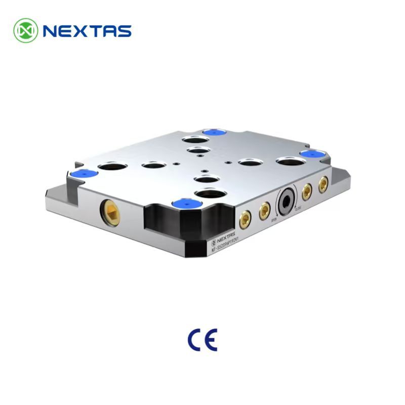
Quick-Change Zero-Point Clamping Plate
Quick-change zero-point clamping plates in 52 mm and 96 mm modular formats for vises, pallets and fixtures, with fixed indexing and fast manual unlocking.
View product →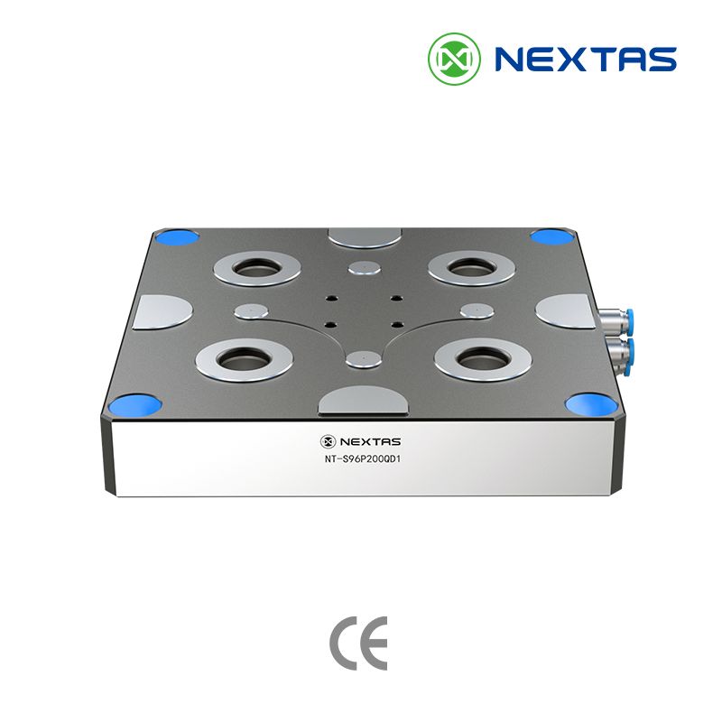
Pneumatic Zero-Point Plate
Pneumatic zero-point plates for CNC automation, pallets and fixture changeovers, with spring locking, pneumatic release and repeatable positioning.
View product →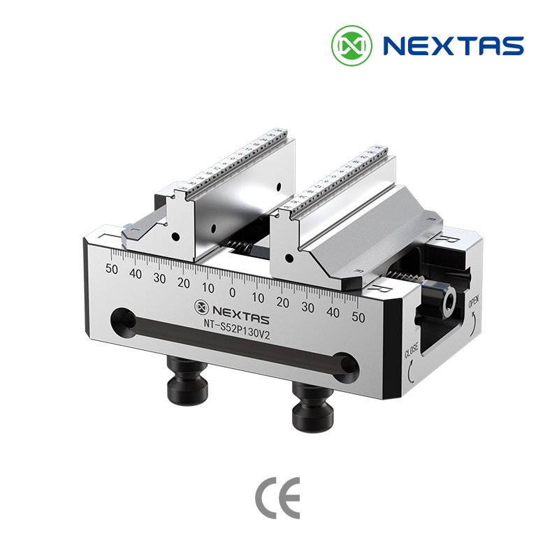
High-Precision 5-Axis Self-Centering Vise
High-precision 5-axis self-centering vises in 52 mm and 96 mm systems, built for modular quick change, automation loading and stable multi-side machining.
View product →Comparing zero-point plate options?
Share your plate size, machine interface, and changeover goals. We’ll help review standard and custom plate layouts for repeatable positioning and faster setup swaps.
Review Plate Layout Options →