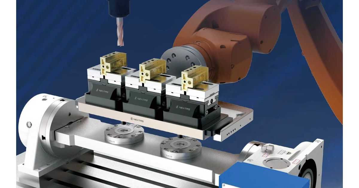
Buyer decision
Do not approve a pneumatic vise because it can close on command. Approve the whole clamp path only when the air circuit, feedback, PLC permissions, jaws, part and fault response have passed a written test.
This is a design and test guide. It is not a customer case, a production result or approval for a complete machine cell.
Start with the air path, not the M-code
A pneumatic vise uses compressed air to move its clamp mechanism. That makes automatic actuation possible. It does not make the air supply stable or the circuit complete.
Map the path from the plant header to the vise. Include the shutoff, air preparation unit, regulator, gauge, valve, tubing, fittings and exhaust. Show the hose route through the machine. Check for pinch points, hot chips, coolant and moving axes.
Pressure at the plant header is not the same as pressure at the vise during motion. Tube length, valve flow, several devices moving at once and a blocked exhaust can change the response. Record the supply range and flow needed by the selected model. Use the quoted drawing or product data. Do not copy a value from another vise size.
Set ownership as well. Maintenance needs to know who may change the regulator, how the setting is locked, how water is drained and when a leak becomes a stop condition.
| Air-path item | Question | Evidence to keep |
|---|---|---|
| Supply | Does pressure stay in the accepted range during the real sequence? | Logged trial at the point of use |
| Valve and tubing | Can the circuit move and exhaust as the model requires? | Circuit drawing and timed test |
| Service route | Are hoses and wires clear of tools, chips and axes? | Machine-envelope review |
| Settings | Who can change them, and how is a change recorded? | Locked setup sheet |
Define what “clamped” means in this cell
A close request is one bit. An accepted clamp state is an engineering decision. The team must decide which facts are needed before cutting begins.
A pressure switch can show that pressure crossed its set point. It may not show that the jaws reached the expected position. A position switch can show motion at one point. It may not show that the part is seated on its datum. A part-present sensor can find a part, but it may not prove usable jaw contact.
List each signal and write one plain sentence about what it proves. Then list what it does not prove. This prevents a broad signal name such as “vise OK” from hiding an unchecked condition.

Build a small signal matrix
The controls engineer should not have to infer signal meaning from a wiring label. Use a matrix that joins the physical state, input, timeout, permission and fault response.
| State or input | What it may prove | What it does not prove alone |
|---|---|---|
| Supply accepted | Pressure is above the chosen switch point | Part seating or jaw position |
| Open position | The selected open-state sensor changed | Robot path is clear |
| Clamp position | The selected clamp-state sensor changed | Grip is adequate for the cut |
| Part present | The part reached the sensing zone | The datum is clean and seated |
| Robot clear | The robot control reports its agreed position | All other cell hazards are controlled |
Sensor ports and feedback options vary by vise model and circuit. Confirm what the selected hardware provides. If a required state has no direct feedback, record the added sensor or test method. Do not turn an absent signal into an assumed pass.
Make the PLC handshake a chain of permissions
A PLC, or programmable logic controller, coordinates the machine inputs and outputs. A CNC M-code may ask the PLC to open or close the vise. The PLC still needs to check the agreed conditions before it drives the valve.
- Exchange request. The CNC reaches the defined load state.
- Open permission. Conflicting machine motion is blocked under the cell logic.
- Open request and proof. The valve changes state. The PLC waits for the required open evidence.
- Robot load. The robot places the part and reaches its agreed clear state.
- Clamp request and proof. The PLC drives the clamp request and checks the required pressure, position and part evidence.
- Cycle permission. Machining starts only when all required states agree and no timeout is active.
Name the owner of every bit. State whether it is a request, feedback or permission. Add a timeout and fault code to each motion. The reset rule should return the cell to a known step, not skip the missing proof.
Treat missing or contradictory feedback as a fault
Plan tests for the states that normal production should never show. The clamp command may be on while clamp feedback stays off. Open and clamp feedback may appear together. Supply pressure may fall after the accepted state. The robot-clear input may disappear before cycle start.
When required evidence is missing or contradictory, the controls should block the next permission. The exact stop and energy response depend on the full cell design. Keep the failed step and input state in the alarm record so staff do not have to guess.
Do not assume what the vise does after an air loss. Some circuits may hold a state, some may move and some may become uncertain. Use the selected-model documents and pneumatic schematic. Test the real circuit under the site procedure.
Prove the jaws and part, not only the device
Even correct signals cannot prove that a jaw design suits the cut. Review the real part, jaw contact, grip height, material, wall thickness and cutting load. Include the effect of chips on the datum and part pickup.
Set the regulator only from an approved process plan and selected-model data. More pressure is not a substitute for jaw support. Too little grip can allow movement. Too much input can mark or distort some parts. The acceptable range must come from testing the actual part and process.
Inspect the features that matter after repeated clamp cycles. Include a planned stop and recovery in the sample. Record the jaw set, regulator setting, tool path, measuring method and result.
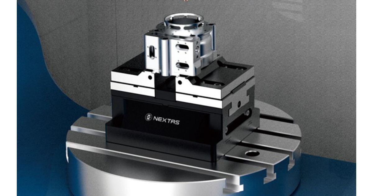
Release the clamp path with normal and fault tests
Begin with document control. Keep the exact vise model, mounting drawing, jaw drawing, air schematic, valve details, sensor list, PLC revision and alarm list together. Mark any value that is still waiting for supplier or site confirmation.
Run the normal sequence with representative parts. Record open and clamp times, supply state and each feedback transition. Then introduce one planned fault at a time. Remove a sensor input, restrict the supply within a controlled test, prevent full seating, interrupt the sequence and restart under the written recovery method.
The purpose is not to force the cell to continue. It is to show that a missing proof blocks the next step and creates a clear alarm. Qualified staff must plan and control these tests.
- The exact vise, valve, sensor and jaw configuration matches the documents.
- The point-of-use air supply stays within the accepted range during the sequence.
- Each command, feedback and permission has one clear meaning.
- Timeouts and contradictory signals block cycle start.
- The selected failure state is tested under the site procedure.
- Part inspection meets the site’s written process limits.
- Recovery returns to a known state before automatic motion resumes.
Complete-cell safety boundary
A pneumatic vise and its feedback do not approve a CNC or robot cell. A qualified machine builder or integrator must validate guarding, interlocks, safe access, energy control, robot motion, machine interfaces and recovery for the real site. Product data supports that work; it does not replace the cell risk assessment.
What NEXTAS can review
NEXTAS lists pneumatic vise families for CNC automation, including several body sizes. Model-specific pressure, force, mounting and sensor details must be confirmed for the selected quotation and drawing.
For an interface review, send the part and jaw drawings, expected machining load, machine space, mounting pattern, available air data, valve and I/O details, robot sequence and required feedback. NEXTAS can review the workholding interface. The machine builder or integrator remains responsible for controls and complete-cell release.
Questions before controls release
Does a pneumatic vise prove that a part is clamped?
No. An open or close command only asks the device to move. The cell needs defined evidence for the selected vise state, part seating and robot clearance before it permits machining.
Can a CNC M-code control any pneumatic vise?
An M-code can start a control request when the CNC and PLC are configured for it. The output still has to operate the selected valve and read the required feedback. Check the machine I/O, voltage, valve, timing and logic instead of assuming that every controller will work.
Is a pressure switch enough to confirm clamping?
Not by itself. A pressure switch can show that pressure crossed its set point. It may not prove jaw position, part presence or usable grip. The validation plan must state what the pressure signal proves and which other checks are required.
What should the cell do if air pressure falls?
The result depends on the selected vise and pneumatic circuit. Confirm the documented state during supply loss, then test that condition under the site procedure. The controls should block cycle start when required clamp evidence is missing or contradictory.
What data should we send for a pneumatic-vise review?
Send the part and jaw drawings, machining loads, machine space, mounting interface, air-supply data, valve and I/O details, required sensors, robot sequence and planned fault response. Include the exact vise model if one has been selected.
Send one clamp-state sheet
Share the part, jaws, air circuit and I/O list for one machine. We will help identify which vise interfaces are confirmed and which still need evidence.