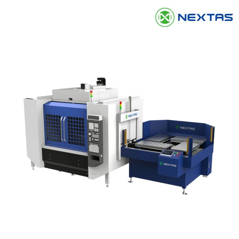


Enter your work email to open the 2026 product catalog immediately.
Air-actuated zero-point plate for robot loading, pallet transfer and automation-ready fixtures
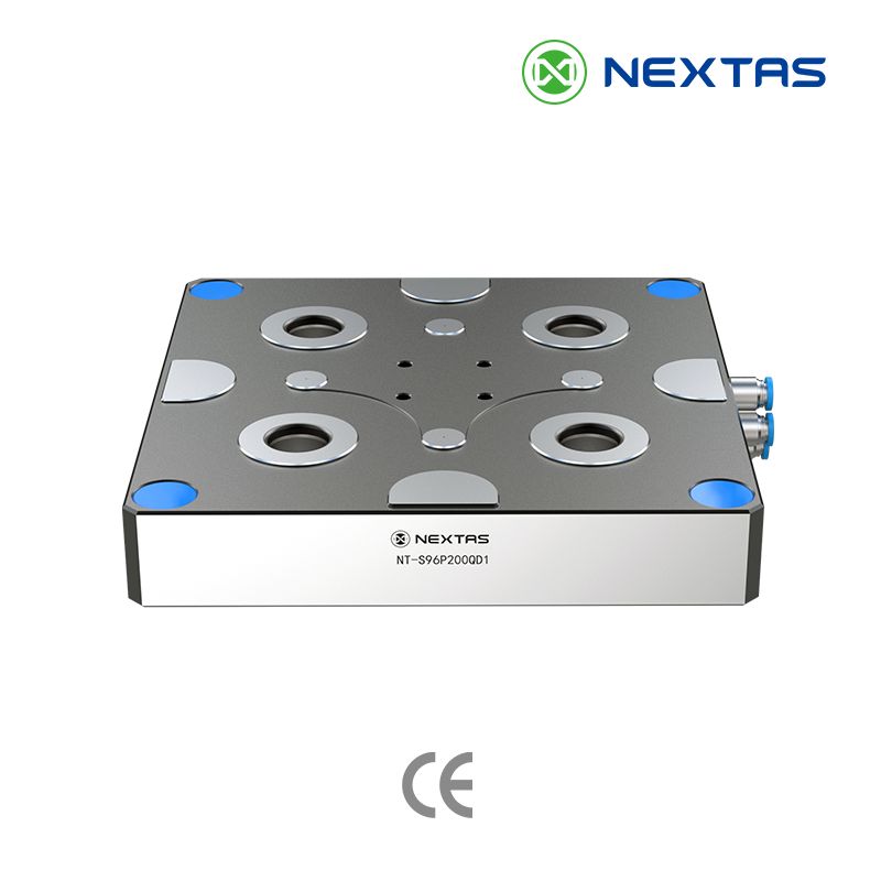
The NEXTAS Pneumatic Zero-Point Plate provides a repeatable interface intended to shorten fixture and pallet changeover. It can support robot or APC workflows when the selected model, pull studs, fixture stack-up, air circuit, sensing, interlocks, and complete cell sequence are verified before production.
Choose the pneumatic version over the manual zero-point clamping plate when robot- or APC-controlled release is required. Listed pneumatic models use pneumatic release, and applicable configurations may add lift-on-release. Published repeatability is <0.005 mm; verify the exact model, pull-stud geometry, load, circuit, and cell logic. For loose receiver modules to integrate into your own subplate, see Zero-Point Clamping Systems.
Engineering boundary: Published values are model-specific, and a 52/96 mm pitch alone does not prove interchangeability. Release the selected assembly only after verifying the approved drawing, pull-stud geometry, load, air circuit, clamp-state monitoring, interlocks, and complete machine/cell risk assessment.
Best fit
Choose this plate when uptime loss comes from fixture swaps
Best for palletized tombstones, robot-loaded fixtures, and repeat jobs where the machine should stop waiting for re-indicating.
Compare first
Confirm pull-stud standard, station count, and air logic
Most buyers decide faster once 52 / 96 mm spacing, fixture footprint, and air or sensor needs are clear before going deeper into tables.
Need next
Jump straight to the decision sections
Use the quick links below to compare selection, integration, and maintenance without getting lost in the full page.
A practical checklist for choosing a pneumatic zero-point plate (air-released, spring-locked) and integrating it into pallet systems, APCs, and robotic cells.
Use matching, approved pull studs on each pallet or fixture so operators can prepare work offline and use “drop-on & clamp” on each verified machine. Confirm the receiver geometry, mounting pattern, orientation, and load for every machine; use locating pins only as defined in the approved drawing.
Use clean, dry compressed air and place a regulator close to the machine. For automation, add valve sequencing and I/O logic so the machine/robot only starts when clamp status is confirmed.
Validate repeatability over multiple cycles: clamp/unclamp, probe the datum, and record deviations. Use the results to evaluate whether the selected plate, fixture stack-up, and installed process meet the tolerance requirement.
Use the production outcome checks to compare the proposed setup with your current process. Actual results depend on part geometry, fixture stack-up, cutting parameters, and the automation sequence.

Measure re-touching after re-clamp in the actual multi-operation workflow. Compare the result with your current process; the selected plate, fixture stack-up, mounting, and environment determine installed performance.
Check the selected plate’s clamping rating against cutting loads and fixture overhang. Confirm the approved circuit, clamp monitoring, interlocks, and complete machine risk assessment before cutting.
Measure the complete swap sequence against the current manual indicating and alignment baseline; no fixed changeover time is assumed. Include the pallet, valve, sensors, handling system, and validated control sequence.
Verify the interface on every CNC, EDM, or inspection station in the proposed robot route. Confirm the selected model’s documented air-tightness and cleaning options together with complete cell controls.
The six listed models publish <0.005 mm repeatability and model-specific load data. Changeover, sealing, coolant or chip resistance, and installed reliability depend on the selected configuration, environment, maintenance, and validated process.
Reference models aligned with the current catalogue. 52 mm and 96 mm interfaces are both available for automated pallet, fixture, and robot-ready changeover planning.
| Model | Stud standard | Repeatability | Clamping force | Lifting load | Unlocking pressure | Spigot | Weight |
|---|---|---|---|---|---|---|---|
| NT-S52P125QD1 | 52 mm | <0.005 mm | 9,000 N | 100 kg | Confirm drawing | NT-S52P16V1 | 3.5 kg |
| NT-S52P168QD1 | 52 mm | <0.005 mm | 9,000 N | 100 kg | Confirm drawing | NT-S52P16V1 | 5.2 kg |
| NT-S52P229QD1 | 52 mm | <0.005 mm | 18,000 N | 200 kg | Confirm drawing | NT-S52P16V1 | 6 kg |
| NT-S96P200QD1 | 96 mm | <0.005 mm | 20,000 N | 280 kg | Confirm drawing | NT-S96P20V1 | 9 kg |
| NT-S96P250QD1 | 96 mm | <0.005 mm | 20,000 N | 280 kg | Confirm drawing | NT-S96P20V1 | 12 kg |
| NT-S96P400QD1 | 96 mm | <0.005 mm | 40,000 N | 560 kg | Confirm drawing | NT-S96P20V1 | 18 kg |
The model tables list <0.005 mm repeat positioning. NT-S96P200QD1 and NT-S96P250QD1 list 280 kg lift load; NT-S96P400QD1 lists 560 kg. The individual sheets do not specify unlocking pressure; confirm it with the selected drawing and circuit. Lift load is not a cutting-load or complete-cell payload rating.
The six reference models list hardened stainless-steel bodies, pneumatic release, a mechanical spring-locking structure, and 4 × 90° fixed indexing. Confirm clamping pressurization, datum cleaning, air-tightness monitoring, sealing, and any auxiliary functions against the selected drawing, circuit, and order scope.

On applicable published models, pneumatic pressure enables release while internal springs drive the clamping slides. The resulting mechanically locked state is intended to maintain clamp when unlock air is removed, but it is not by itself a machine safety function. Confirm the selected drawing, circuit, clamp-state monitoring, interlocks, and complete system risk assessment before production.
Published construction data for applicable models identifies hardened, corrosion-resistant stainless-steel components; selected versions may include sealing and air-blast provisions for chip- and coolant-heavy environments. Confirm the chosen model's sealing, air quality, maintenance, and acceptance requirements, clean locating faces before loading, and validate installed repeatability under actual conditions.

Across machines individually verified to use the same approved interface, palletized workpieces can be transferred by robot between milling, EDM, or CMM steps. Unattended machining remains conditional on the selected model, fixture, gripper, sensing, controls, guarding, interlocks, and validated complete-cell sequence.

The NEXTAS Pneumatic Zero-Point Plate can be integrated with robot-tended fixture or pallet handling. Actual swap time, repeatability, and error rate depend on the selected model, pull studs, fixture stack-up, sensing, controls, and validated cell sequence. Use the model specification table to check the selected plate’s clamping force and lifting load.
The interface can support robot-tended workflows and planning for longer unattended windows. Achievable duration depends on material supply, tool life, sensing, interlocks, exception handling, safety validation, and acceptance of the complete cell.
Practical notes for commissioning an air-released zero-point pallet plate and monitoring installed repeatability through production.
Chips in the locating cones
Where the selected model includes air blast, use it with appropriate coolant management; inspect and wipe the locating faces on a maintenance schedule matched to the environment.
Inconsistent pull studs
Use the approved matching stud type and specified installation torque on each fixture or pallet.
Weak air pressure / leaks
Check regulators, couplers, and hoses; confirm pressure at the plate under load.
Fixture stack-up flex
Reduce overhang, add support, and validate rigidity for your cutting forces.
The examples below show where a selected and validated configuration may support single-machine or automated workflows; suitability and outcomes depend on the complete process.
A verified configuration can support HMC pallet pools by allowing fixtures to be prepared offline; measure any reduction in non-cutting time against the current process.
On a verified fixture stack, the raised workpiece position can improve tool access to five sides of a part and may reduce setups when the selected fixture and process allow it.
The interface can form part of an FMS or robot-tended cell. Fixture exchange logic and any unattended operating window must be engineered and validated for the complete system.
The same verified datum strategy can support transfer from CNC to CMM with less re-clamping. Confirm the selected interface, inspection method, and process capability before relying on transferred coordinates.
A 41-second vertical demonstration of a self-centering vise and pneumatic zero-point plate in an automation context; it is not independent evidence of accuracy, force, or cycle time.
In a representative palletized cell, offline fixture preparation reduced changeover time and increased cutting availability. The actual result depends on the starting process, pallet layout, part mix, and operating discipline, so this is a reference case rather than a guaranteed outcome.

Enter your work email to open the 2026 product catalog for this product family.
Send the exact plate model, approved interface drawing, pallet or fixture load, pneumatic circuit, and intended use so engineering can identify the applicable file set.
It is a datum plate with pneumatic release for repeatable pallet or fixture transfer. It is most relevant when the process needs frequent machine-controlled changeovers, robot loading, or a planned path to pallet automation.
The model tables list <0.005 mm repeat positioning. NT-S96P200QD1 and NT-S96P250QD1 list 280 kg lift load; NT-S96P400QD1 lists 560 kg. The individual sheets do not specify unlocking pressure; confirm it with the selected drawing and circuit. Lift load is not a cutting-load or complete-cell payload rating.
Verify the mounting and locating pattern against the selected drawing, check the installed plate for flatness and orientation, then connect the specified pneumatic circuit. Automated cells also need an agreed valve sequence, clamp-state logic, and machine or robot interlocks before release for production.
Engineering confirms which project-specific 2D or 3D files are available after reviewing the selected model, interface, intended use, and confidentiality scope. STEP, IGES, assembly drawings, or circuit documents are configuration-dependent and are not guaranteed by the website.
The catalogue describes mechanical self-locking and pneumatic unlocking. Confirm the selected model, circuit and air-loss behavior; this mechanism and ordinary clamp or pressure signals do not by themselves establish a safety function. Validate guarding, interlocks, safe state, recovery and acceptance for the complete machine or robot cell.
Clean the locating faces and pull studs before loading, monitor air quality and leakage, and inspect seals, fittings, and wear surfaces on a schedule matched to the real environment. Do not rely on an air-blow feature alone, and confirm the selected model's sealing and maintenance requirements before exposing it to heavy coolant or abrasive chips.
The two datum families make it easier to standardize pallets and fixtures across a shop. Compatibility still requires the exact pull-stud geometry, mounting pattern, load rating, orientation, and stack height to match; pitch alone is not proof that two components interchange.
Share the selected plate model, 52 or 96 mm interface, pallet or fixture load, pneumatic circuit, sensing or option scope, quantity, drawing, and acceptance method. Engineering confirms the schedule and included inspection or traceability records in the quotation or order confirmation; the website does not promise a fixed lead time or complete report with every unit.
Fast quote
Three fields are enough — our engineers reply after reviewing the request with pricing and configuration advice.