Why it fits
Fast clamp/unclamp reduces idle time and keeps cycle timing consistent.
Recommended add-ons
Clamp-OK confirmation (pressure/position), hard jaws, chip-blow air nozzle.
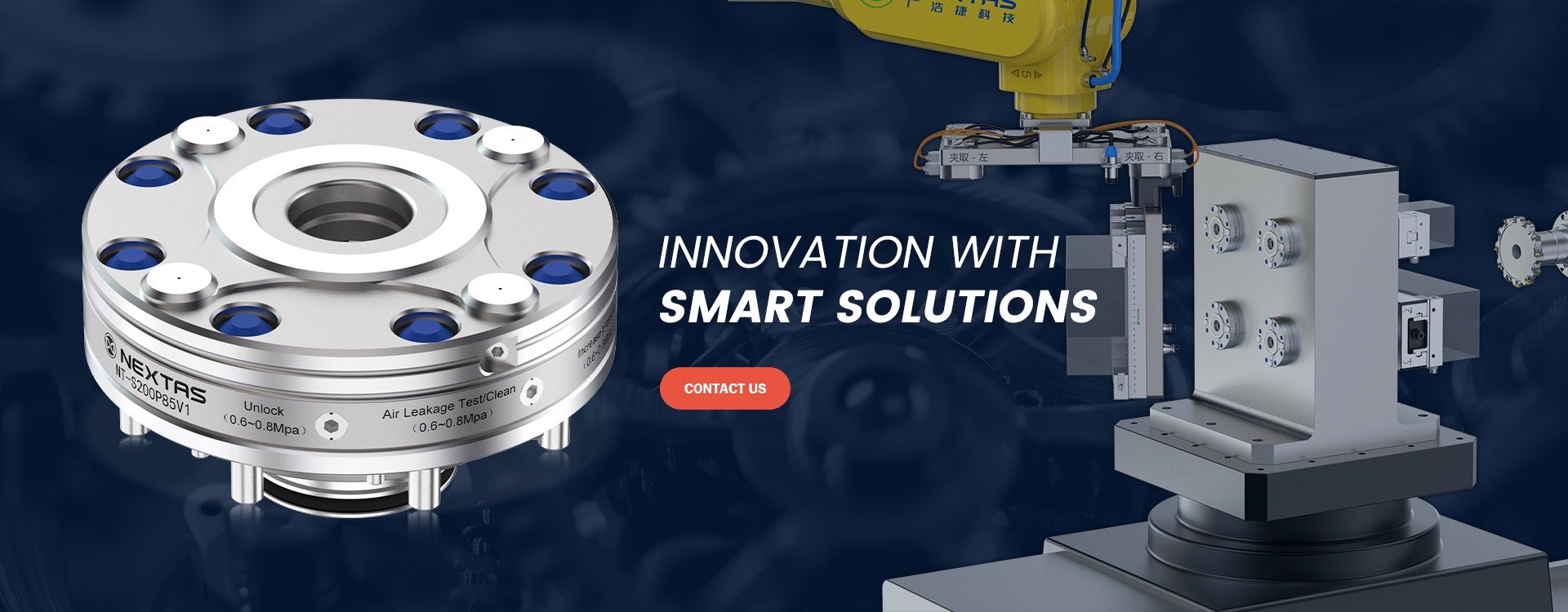
The NEXTAS pneumatic centering vise family covers P75, P110, and P150 so you can size the workholding around part range, clamping force, and automation flow before the fixture concept is locked. Start by choosing the body size, then confirm air or hydraulic actuation, jaw strategy, and pallet or zero-point integration.
Pick this family over the 52/96 mm 5-axis self-centering vise when raw clamp force, hydraulic boost (up to 45 kN at P150), and a 0–250 mm jaw range matter more than five-side tool clearance for compact mold or aerospace parts.
Best fit
A practical match for robot-loaded CNC cells, palletized workholding, and repeat jobs that need faster clamp / unclamp flow than manual vises can provide.
Compare first
That sequence usually resolves the real question faster: compact cell vs heavier cut, air-only simplicity vs hydraulic force, and whether the vise should sit on a pallet or zero-point base.
We size the right pneumatic or hydraulic vise model to your clamping force, workpiece envelope, and production throughput requirements.
Fast RFQ paths
Need drawings or a quick reply? Send air supply, jaw width, and cycle timing directly.
The form arrives pre-filled for the Pneumatic CNC Vise, so your enquiry reaches the right engineer faster.
Tell us the CNC machine model, available air pressure (typically 0.5-0.8 MPa), number of air ports on the table, and whether this is a VMC, HMC, or lathe application.
Share the workpiece shape (round, square, irregular), material and hardness, required jaw width (P75/P110/P150), and the clamping force needed to resist cutting loads.
Specify your target cycle time per part, batch size, whether pneumatic or hydraulic actuation is preferred, and any multi-vise gang mounting or automation plans.
The catalogue lists three self-centering vise sizes with pneumatic and hydraulic variants, making it easier to shortlist by workpiece envelope, cutting load and available machine space instead of forcing a one-size-fits-all choice.
| Model | Product code | Actuation | Working pressure | Repeatable clamping accuracy | Clamping force | Adjustment range | Weight |
|---|---|---|---|---|---|---|---|
| P75 | NT-S75P75V1 | Pneumatic | 0.5–0.8 MPa | <0.01 mm | 4,200 N | 0–125 mm | 7 kg |
| P75 | NT-S75P75V2 | Hydraulic | 6 MPa | <0.01 mm | 9,000 N | 0–125 mm | 7 kg |
| P110 | NT-S110P110V1 | Pneumatic | 0.5–0.8 MPa | <0.01 mm | 12,000 N | 0–200 mm | 24.9 kg |
| P110 | NT-S110P110V2 | Hydraulic | 6 MPa | <0.01 mm | 30,000 N | 0–200 mm | 24.9 kg |
| P150 | NT-S150P150V1 | Pneumatic | 0.5–0.8 MPa | <0.01 mm | 20,000 N | 0–250 mm | 41.6 kg |
| P150 | NT-S150P150V2 | Hydraulic | 6 MPa | <0.01 mm | 45,000 N | 0–250 mm | 41.6 kg |
Best for smaller parts, tighter robot access, or machines where table space is limited.
A good fit for general CNC production where you need more range and force without jumping to the heaviest body size.
The largest family is the right starting point for larger workpieces, stronger roughing loads, and more demanding automation cells.
Holds the part through robot load and unload, so a cell can run lights-out for long stretches without anyone resetting clamps.
Clamps to the same point every cycle in automotive and electronics work, which keeps parts in tolerance and trims seconds off each load.
Pairs with pallet changers so several workpieces run through one setup instead of several.
Keeps the workpiece steady under high-feed, deep cuts — the kind of load you hit in mold roughing.
Use this matrix to decide where a pneumatic-hydraulic vise adds the most value—especially in lights-out machining, palletized systems, and robot loading.
A practical checklist for choosing a pneumatic self-centering vise and integrating it into robotic CNC cells, pallet systems, and high-mix production—without sacrificing repeatability.
Choose jaws based on how you want to locate the part (OD/ID, flats, or custom profile) and how often you will change part families.
A robot should never load/unload against an unknown clamp state. These are common signals used with an automation-ready pneumatic vise.
Stable air supply and basic housekeeping are what keep a pneumatic vise predictable in automation. Use this as a quick commissioning + upkeep checklist.
Simple, consistent checks keep a pneumatic-hydraulic vise stable in unattended machining. Use this table as a shop-floor routine.
JAW SWAP GUIDES
Two short visual guides for the team that runs the cell — flip hard jaws or mount soft jaws without pulling the manual every time.
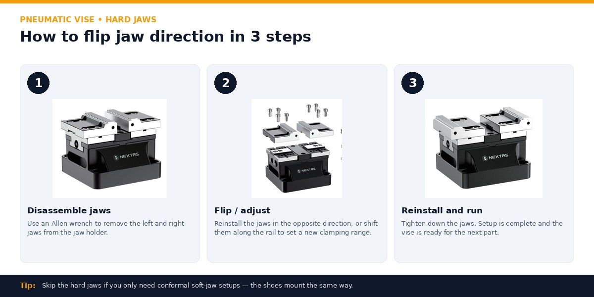
Hard jaws — 3 steps
Re-orient hard jaws to switch between front-face and back-face clamping, or to set a different clamping range.
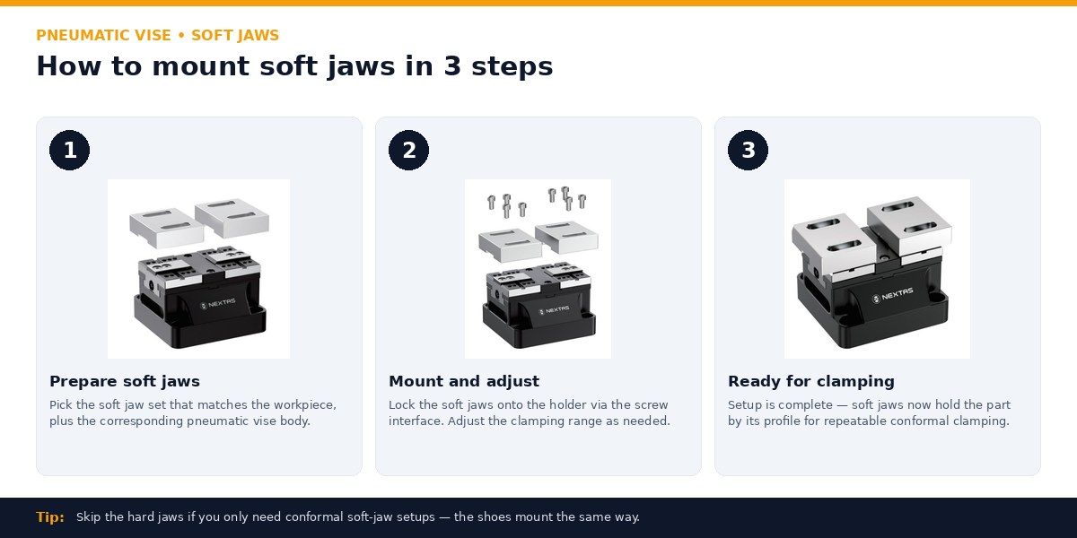
Soft jaws — 3 steps
Mount conformal soft jaws so the part is held by its profile — repeatable on irregular shapes.
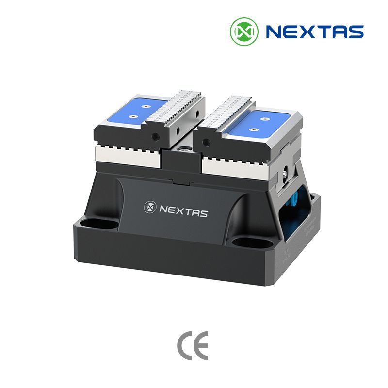
Pneumatic vises in production — clamping prismatic parts for HMC roughing, multi-vise tombstone setups, and robot-loaded 24/7 cells.
The NEXTAS pneumatic centering vise is a workholding device built for automated CNC environments and repeat production. It suits mid-volume machining cells where clean shop air is already on the floor and clamp / unclamp has to run through PLC or M-code without an operator.
Three body sizes — P75, P110 and P150 — with jaw opening from 0–125 mm up to 0–250 mm. Clamping force runs from 4,200 N (P75 pneumatic) to 45,000 N (P150 hydraulic), with repeatability under 0.01 mm. Pneumatic models run on 0.5–0.8 MPa shop air; hydraulic models run at 6 MPa.
It is compatible with CNC machining centers, milling machines, and can be integrated with ITS systems for automation.
Installation is via standard keyways and mounting holes on T-slot tables. It also has pneumatic/hydraulic interfaces and locating pins for precise setup.
If you need STEP/IGES or 2D drawings, please Contact us.
A key advantage is that this vise family gives you both pneumatic and hydraulic choices in the same centering-vise format. That lets you balance plant utilities, target clamping force, and automation simplicity without changing the overall workholding concept.
Catalog-listed P75 / P110 / P150 models are specified at <0.01 mm repeatable clamping accuracy, which supports consistent automated changeovers.
FCD60 is a high-tensile ductile iron. This material provides excellent rigidity and vibration-damping capabilities. During heavy-duty cutting, it effectively absorbs machining vibrations, ensuring stability, a superior workpiece surface finish, and extending the vise's long-term durability.
Use clean, dry, filtered air (FRL) and keep pressure stable in the recommended 5–7 bar range. For robotic cells, drive clamp/unclamp via a solenoid valve (PLC/M-code) and add confirmation using pressure or position sensors.
Use hard jaws for repeatable production clamping and soft jaws when you need a custom profile. For best accuracy, machine soft jaws in-place, keep jaw seats clean, and standardize jaw changeover torque and locating features.
Yes. Mount the vise on a zero-point clamping plate or pallet to speed up fixture swaps and keep referencing consistent across machines—especially useful for HMC pallet systems and high-mix production.
Keep chips/coolant away from sealing and seating surfaces, inspect wipers/seals regularly, and verify repeatability with a gauge block or reference part. Record baseline clamp time/pressure so you can spot drift early.
Standard P75, P110, and P150 pneumatic vises ship in roughly 15–25 days after PO confirmation. Custom jaw profiles, matched pairs, or hydraulic-actuation conversion add about a week. Committed lead time is confirmed in writing once the body size, jaw style, and actuation are locked.
Each vise ships with a factory inspection report covering jaw parallelism, base flatness, and clamping-force measurement at the rated air pressure. Material certificates for the hardened body, hydraulic-actuator certificates where fitted, and the written warranty are available on request at order time.
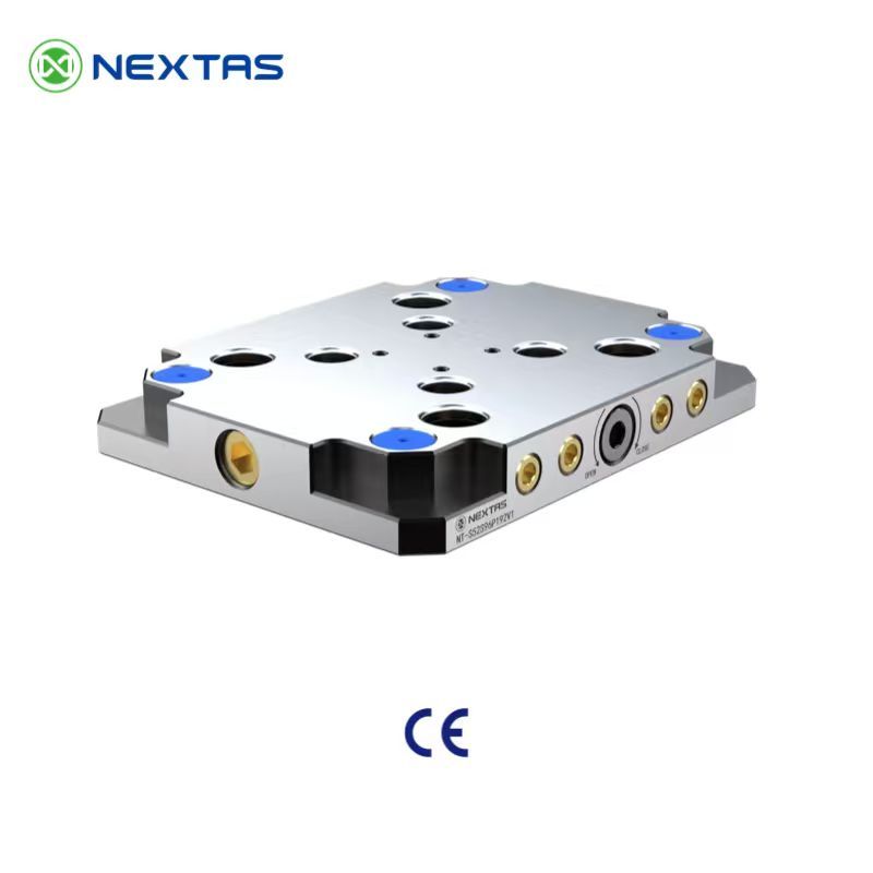
Standardize the machine-side datum before adding pneumatic workholding to mixed CNC setups.
View Details →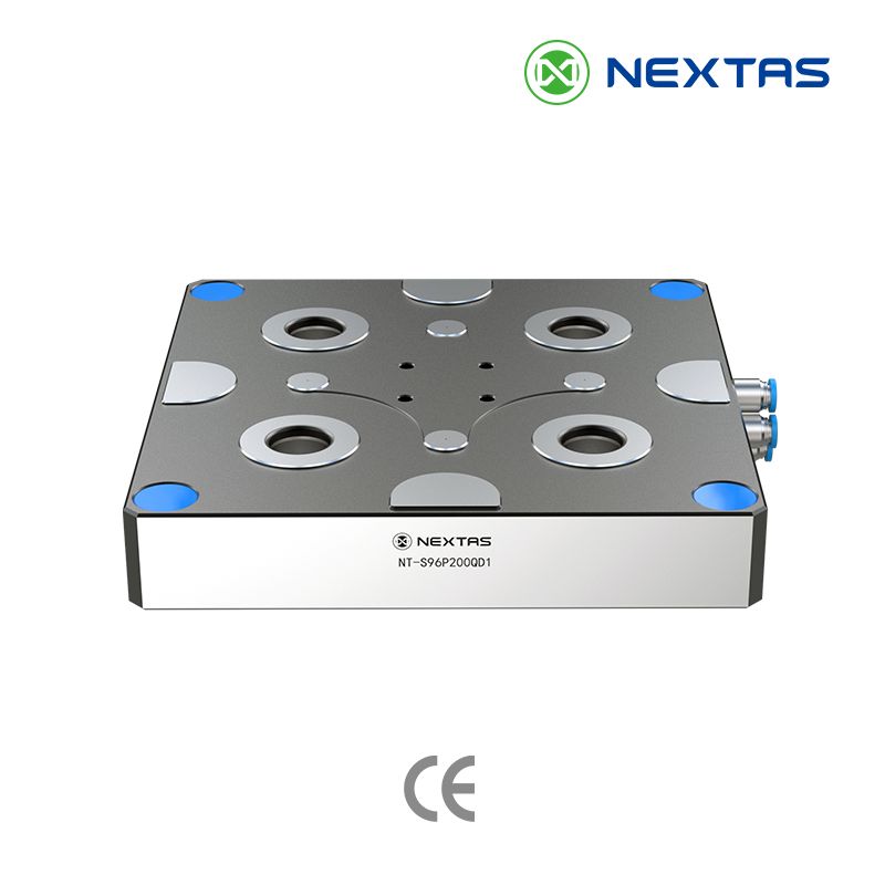
Combine machine-controlled clamp/unclamp with pneumatic vises when the full fixture stack must cycle automatically.
View Details →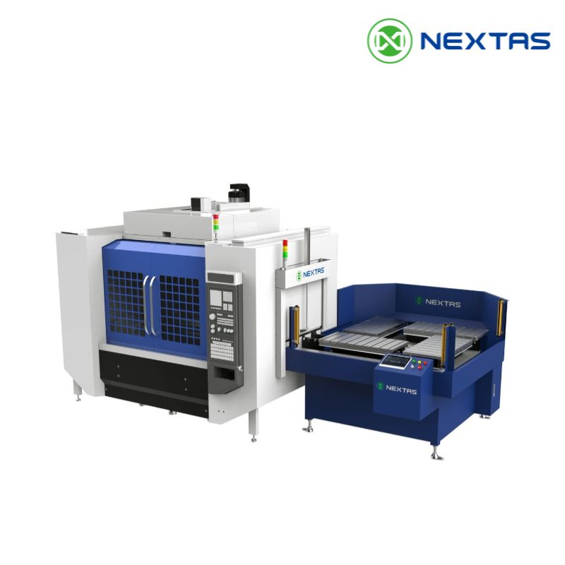
A strong next step once pneumatic clamping is standardized and the target shifts toward unattended pallet turnover.
View Details →Fast quote
Three fields are enough — our engineers reply within one business day with pricing and configuration advice.