Thin-wall or distortion-sensitive parts
Balanced clamp points, hydraulic work supports and staged or multi-zone pressure help protect critical geometry.
Engineered workholding for stable clamping, CTQ protection and automation-ready machining flow.
Choose a custom hydraulic fixture when the part family, datum chain, or takt target no longer fits a standard vise or modular clamp. NEXTAS engineers the locating logic, clamping points, hydraulic circuit, and automation handoff around the real cutting sequence so the fixture supports the process instead of forcing compromises.
Best fit
A strong fit for multi-station machining, protected datums, thin-wall parts, and projects where locating logic, chip protection, or automation sensing must be engineered together.
Start here
That input usually clarifies whether the concept needs swing clamps, work supports, pull-down logic, sensor feedback, pallet coupling, or a more service-friendly manifold design.
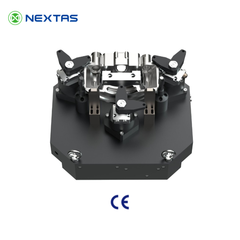
Project fit
Use these decision points to judge whether a part-specific hydraulic workholding system is the right route for your machining process, production volume and automation plan.
Balanced clamp points, hydraulic work supports and staged or multi-zone pressure help protect critical geometry.
Controlled hydraulic pressure reduces operator variation when force and datum stability must remain consistent.
Quick couplings, part-present sensing and clamp-position confirmation support APC, zero-point and robot-loaded cells.
Part-specific locating, chip evacuation and clamp sequencing keep tools clear across multi-face and multi-station operations.
These four inputs usually reveal the right fixture path before detailed engineering begins.
Integrated engineering
The locator scheme, clamping sequence, hydraulic circuit, sensing and power unit are reviewed together so datum stability, tool access, service access and automation interlocks support the same process.
Use 3-2-1 or a custom CTQ datum strategy around part stiffness and cutter access.
Select swing, pull-down or toe clamps, work supports and anti-lift elements.
Plan manifolds, sequence valves, pressure retention and pressure confirmation.
Coordinate PNP/NPN sensors, M-code or PLC logic, rotary unions and through-pallet routing.
Configuration map
Configure the core building blocks around the part family, operations and control architecture. Final selections follow drawing and machine review.
Tool access, chip escape, coolant routing, service clearance and safe unclamp logic are reviewed with every architecture.
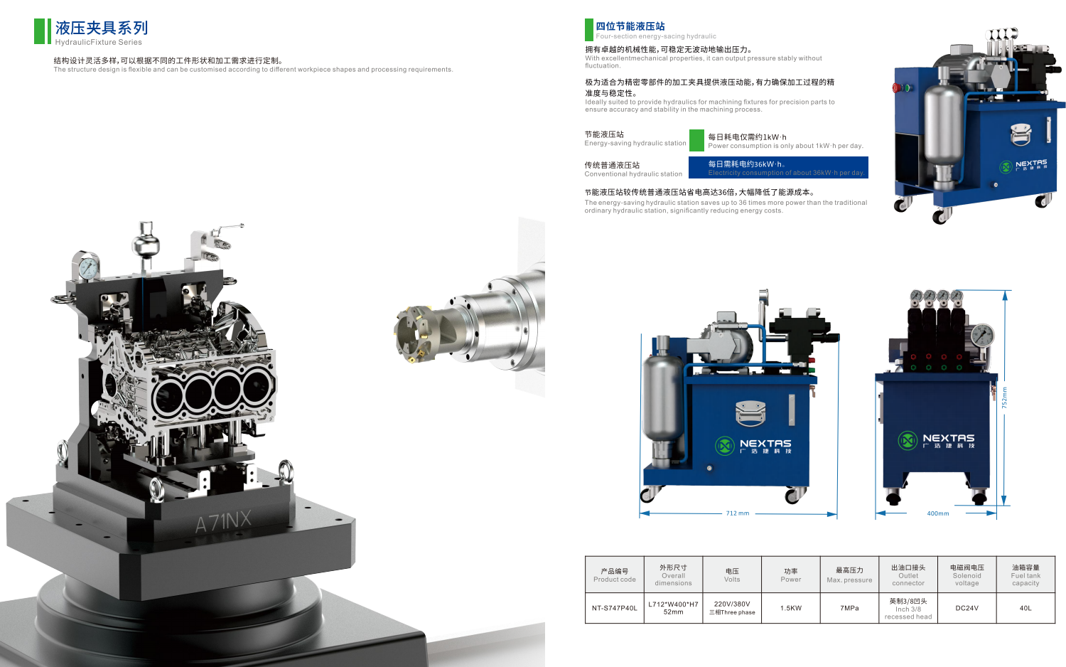
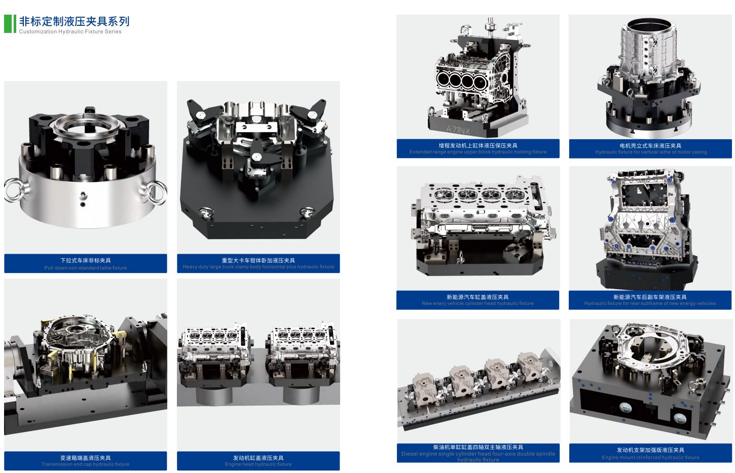
Fixture architecture portfolio
The layout follows the part, datum strategy, tool access, stiffness and production sequence.
Selection data
Published ranges frame the review. Final values depend on geometry, cutting loads, clamp arrangement, circuit design and acceptance criteria.
| Fixture body | High-grade alloy steel or aircraft-grade aluminum |
|---|---|
| Clamping components | Hardened tool steel, HRC 58–62 |
| Actuation | Single- or double-acting hydraulic actuation |
| Control | Single- or multi-zone; integrated or remote manifold |
| Sensors | Part-present, clamp-position and pressure-confirmation feedback |
| Finishes | Black oxide, nitriding or nickel plating |
| Fluids & seals | Mineral oil or water-glycol compatibility by seal selection; NBR / Viton options |
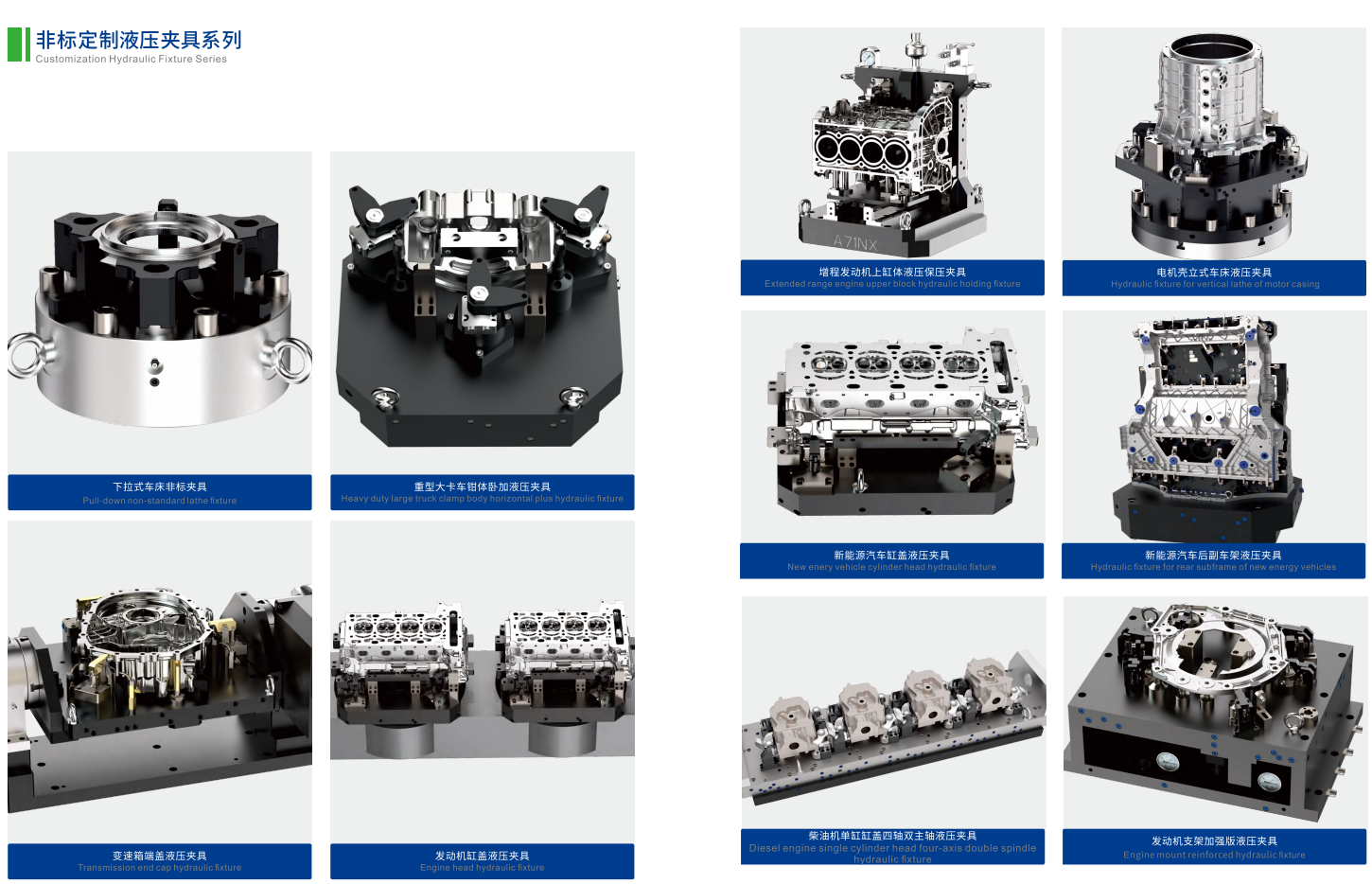
Pairing reference
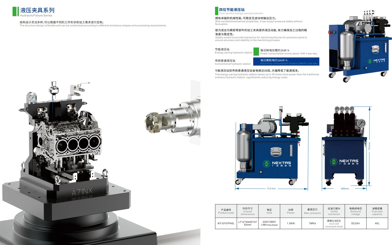
This supplied HPU is a 7 MPa reference, not a substitute for project-level sizing across the broader 10–70 MPa custom-system range.
Some fixture circuits may also be reviewed in the 70–210 bar range. Final pressure and flow follow circuit and clamp-force review.
Engineering workflow
A clear review sequence aligns the fixture, circuit, machine interface and validation evidence before release.
Part, process, machine and targets.
Datums, access and clamp concept.
Pressure, sequence and interlocks.
Precision build and verification.
Leak, force and repeatability checks.
Documents, spares and commissioning.
Documentation follows the agreed project scope and buyer review points.
Lifecycle support
Separate circuit, clamp, locator and sensing issues before changing the fixture concept.
Confirm pressure and flow, regulator setting, hose routing and clamp sequence. Inspect for pressure loss before changing clamp geometry.
Verify locator contact, clamp direction, work-support engagement and cutting-load path. Check for chips at datum surfaces.
Inspect seals, fittings and quick couplings; confirm oil condition, pressure and valve function.
Review clamp positions, staged pressure, locator strategy and sensor alignment. Reconfirm setpoints after maintenance.
Technical answers
Answers to common questions about custom hydraulic fixture systems.
It’s a CNC workholding solution designed around your specific part and process. Using hydraulic pressure, it clamps with repeatable force and locates datums consistently—ideal for automated or high-volume production.
Hydraulic fixtures typically deliver higher and more stable clamping force than pneumatic systems, with better control for thin-wall parts. Compared with manual/mechanical clamps, they reduce operator variation and improve repeatability in long runs.
Depending on the part, we can integrate swing clamps, pull-down/toe clamps, hydraulic work supports, cylinders, and anti-lift elements. The clamp choice is driven by access, distortion risk, and required cutting loads.
Yes. We often design modular locators and interchangeable clamping elements so a base fixture can accommodate part variants with minimal changeover time.
We balance clamping points, control force with the hydraulic circuit, and design locators around critical-to-quality features. For thin-wall parts, even-force strategies and support elements are used to maintain geometry.
Part drawings (2D/3D), machining ops, datum/CTQ requirements, machine/pallet constraints, automation plan, and production targets (volume, takt time). The more complete the inputs, the faster we can converge on a robust concept.
Fixtures for pallet changers and robotic cells can use quick couplings, standardized manifolds, and feedback for part presence, clamp position, and pressure confirmation. These signals can support process permissives, but they are not safety functions by themselves and do not make unattended operation safe. Before running unattended, validate the sensors, guarding, safety interlocks, safe-stop behavior, fault recovery, and the risk assessment and acceptance of the complete cell.
Routine checks focus on seals, hydraulic connections, and sensor condition. Service-friendly routing and replaceable wear pads help keep preventive maintenance quick and predictable.
Drawing-led engineering review
Send your part drawing, machining sequence, CTQ references and machine or pallet constraints. We will use them to recommend the fixture architecture, hydraulic circuit and control path.