Temporary versus final datums
State which faces locate roughing and which faces become the final reference after heat treatment, grinding or hard milling. Leave the required finishing allowance.
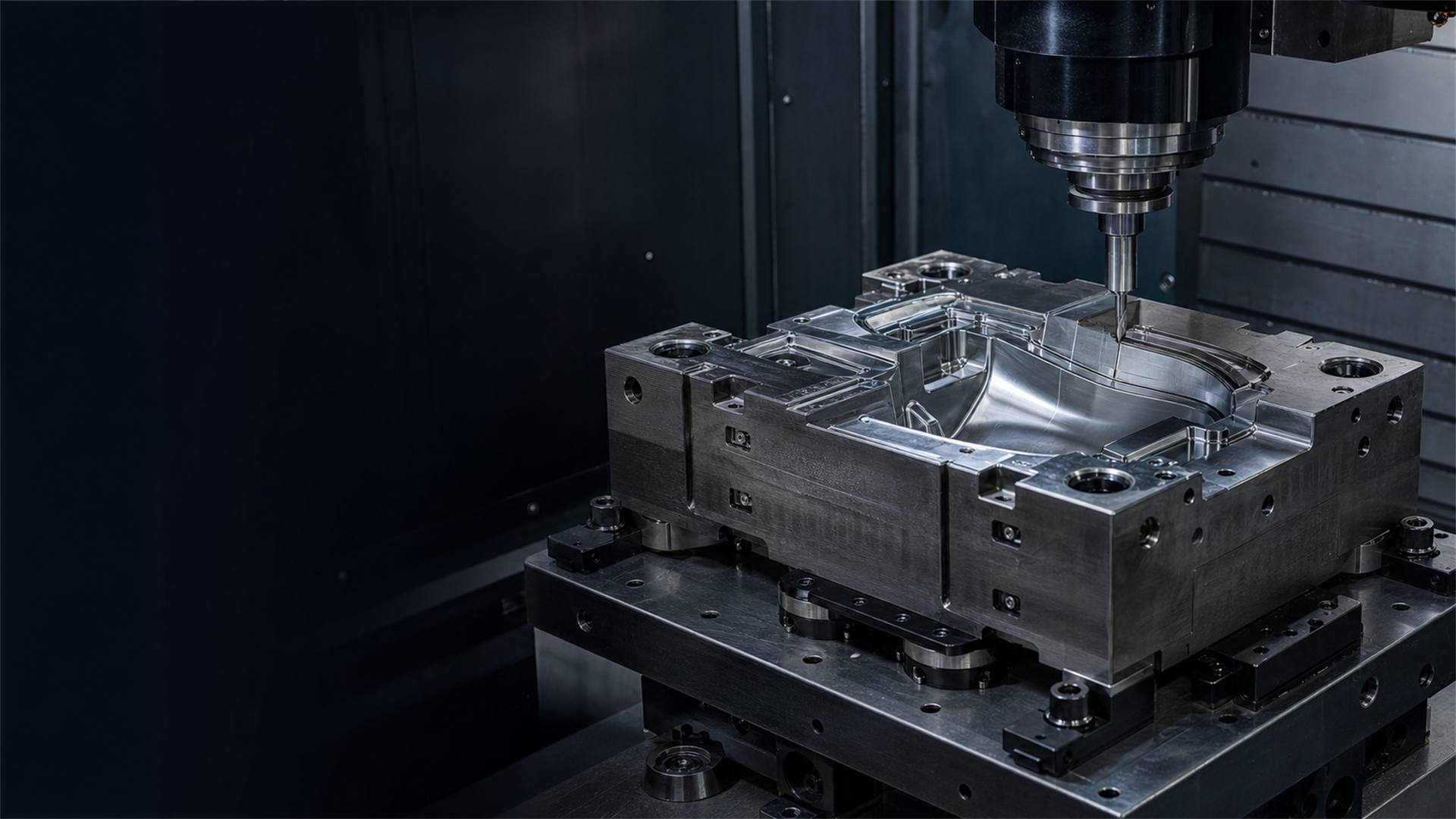
Mold & die / route-based datum transfer
Tool-steel inserts and electrodes may cross milling, heat treatment, grinding, EDM and inspection. Map that route before choosing the carrier and machine-side interface.
Read the route sheet first
A rough tool-steel blank may move during heat treatment. A finish-grinding step may remove an early reference face. An electrode may stay on one holder from preparation to CMM and EDM. Mark where each datum is created, checked, protected and replaced so the fixture does not preserve the wrong reference.
State which faces locate roughing and which faces become the final reference after heat treatment, grinding or hard milling. Leave the required finishing allowance.
Carrier size is only part of the load case. Include workpiece weight, distance from the interface, roughing force, tool approach and EDM flushing or discharge access.
Chips, grinding residue, dielectric fluid and corrosion protection can reach the locating faces. Put the clean-and-check step in the route rather than leaving it to operator memory.
Separate datum from hardware
Electrodes, compact carriers and large mold inserts do not need the same interface. Start with the stations, load path and access, then confirm both mating drawings.

Route for electrodes and compact carriers
The E-Series is aimed at electrode and precision-carrier transfer across compatible EDM, WEDM, grinding, presetting and inspection stations. Treat it as one side of a complete interface, not as a universal chuck that accepts anything carrying an ITS label.
Route for a compact fixture carrier
Route for larger bases and inserts
Interface evidence pack
A chuck specification does not cover the holder, adapter, machine table and inspection method. Put those items on one interface drawing and test the route that production will run.
Show machine table, chuck or receiver, adapter, holder or pallet, fixture and part. Add Z heights, bolt patterns, locating faces, orientation and utility access.
Record total weight, center-of-mass projection, roughing load, toolholder sweep, EDM approach, flushing space and any robot gripper clearance.
Remove, clean, reload and measure the carrier at each milling, EDM, grinding or CMM station named in the route. Use the same orientation and handling steps planned for production.
Include a heat-treatment inspection, maintenance return or repair loop where relevant. The result should show whether the controlled reference can be recovered without assuming the earlier offset still applies.
Project review
List rough milling, heat treatment, finish work, EDM, CMM, spotting and repair in the order used for this part family.
Provide the machine-side and carrier-side geometry for every chuck, holder, spigot, pallet or adapter. Trade names are not enough.
State what feature is measured after each transfer, which gauge or CMM routine is used and what happens when the result is outside the project limit.
Mold and die workholding FAQ
Yes, when every station accepts the same verified carrier or a documented adapter stack. Check the machine-side chuck, holder or pallet, locating faces, orientation, stack height, load and utility access from drawings. Then remove, clean, reload and measure the carrier at each station used in the route.
No. The E-Series supports ITS-style electrode and pallet workflows, but a family name is not proof of interchangeability. Match the chuck and holder drawings, spigot or pull-in element, locating geometry, Z height, orientation and release method. System 3R is a separate interface family and should not be mixed into an E-Series selection without a documented adapter review.
Heat treatment can move the part, while grinding or hard milling may remove a surface used earlier as a reference. Decide which datums are temporary, where finishing allowance remains and when the final reference is established. Inspect after heat treatment before relying on the carrier for EDM or CMM transfer.
Send the route sheet, part and carrier drawings, material, dimensions, weight, projection from the holder, roughing and finishing loads, EDM approach and flushing space, every machine-side interface, and the CMM datum method. Include any planned heat treatment, repair return or robot handling step.
Start with the transfer chain
Send the route sheet and mating drawings. We will separate the datum strategy, carrier choice and interface checks.