Stock and casting spread
Review the expected raw-part range, not only the nominal model. Keep fixed contacts on stable features and leave clearance around flash, draft, and stock that varies from part to part.
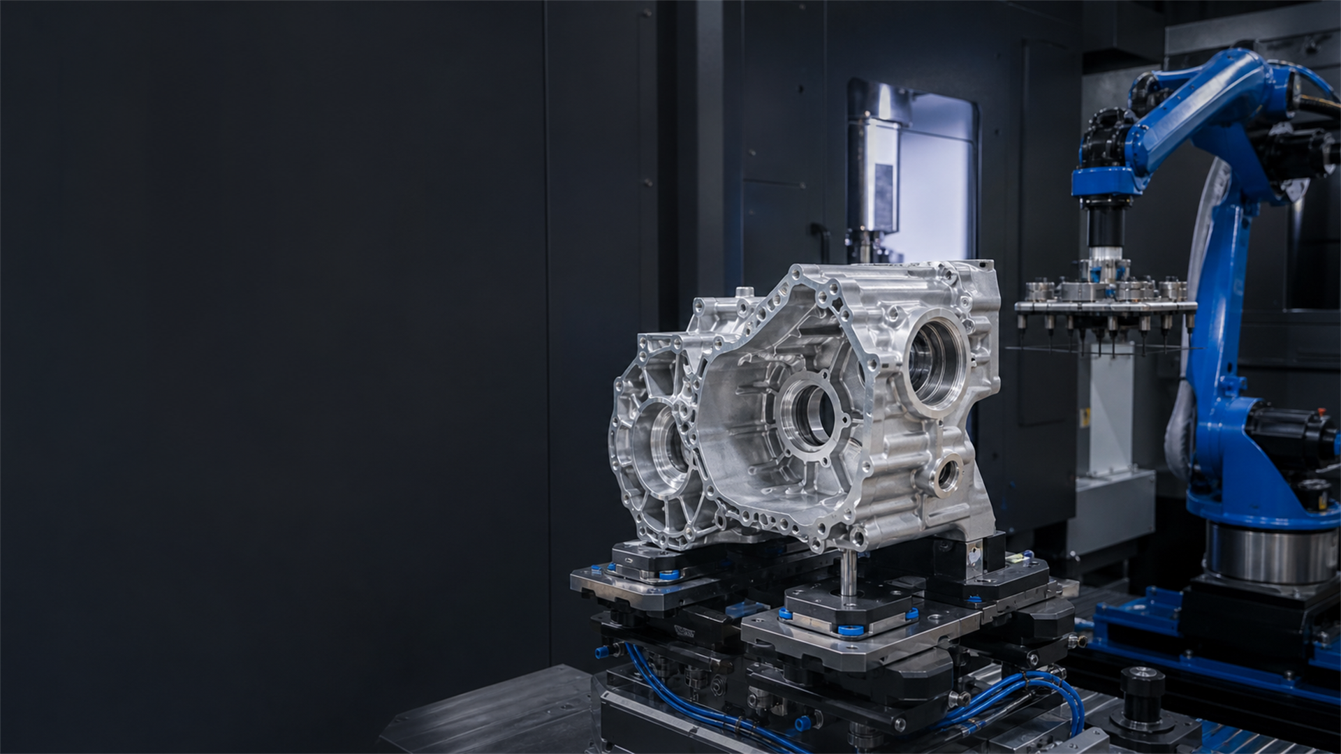
Automotive / cast-part production
Gearbox housings, motor housings, and steering knuckles arrive with real casting variation. The fixture has to locate that raw part, support the machining load, shed chips from contact points, and report enough state for an operator or control system to know what happened.
Design for a real casting
Draft, flash, stock shift, and surface texture can change how a raw housing sits. A rigid nest may rock on one part and pinch another. The fixture plan should name which cast or pre-machined features locate the part, where variation is allowed, and which supports move into place after seating. Chip escape and cleaning access belong in that plan because a trapped chip can change the next load.
Review the expected raw-part range, not only the nominal model. Keep fixed contacts on stable features and leave clearance around flash, draft, and stock that varies from part to part.
Place work supports near the active machining load without lifting or bending the casting. The support sequence must follow seating, locating, and the selected clamp route.
Add paths for chips and coolant to leave the nest. Make contact points visible or cleanable so an operator can inspect them after a fault or during planned service.
Station architecture
Actuation is one layer of the station. The part family, raw variation, locator scheme, support sequence, utilities, inspection route, and restart method decide whether a dedicated fixture, common base, or pallet handoff belongs in the layout.
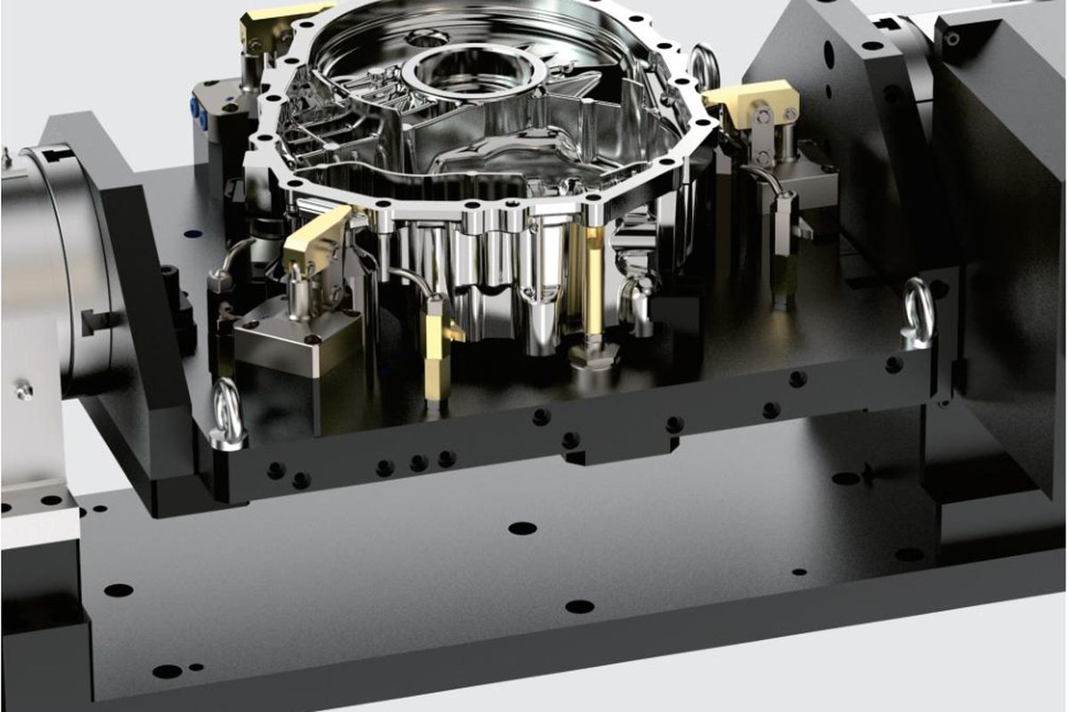
Part-specific station
A custom hydraulic fixture can combine fixed locators, work supports, clamp arms, manifolds, and state feedback around one casting family. It fits recurring production when the operation order and machine interface are known. Circuit pressure, clamp force, support type, sensor set, and maintenance access still come from the project review.
Fixture layout reference
This 28-second vertical video shows the visible layout of a multi-station fixture for repeated part loading. It is a general fixture example, not a published customer case, hydraulic schematic, sensor map, or performance test.
Continue to Station InputsStandardize the base
Move prepared pallets
Runoff plan
A clean dry cycle does not show what happens after chips reach a locator, a casting sits at one edge of its raw range, or the station stops halfway through clamping.
Run the named casting condition through the planned sequence and inspect the critical machined features. Record the locator, support, clamp, program, and inspection revisions.
Load parts from the expected casting range with representative operators or the planned robot path. Check seating, orientation, support contact, and the measured features after cutting.
Define the part-present, clamp-position, support-contact, and pressure states used by the process. A clamp signal is process feedback; it does not replace the machine safety functions for the complete cell.
Interrupt agreed steps and follow the written restart route. The machine and fixture should return to the states required by the cell risk assessment before cutting or transfer resumes.
Scope the station
Show how the raw casting arrives, which side faces the operator or robot, and where hands, grippers, or lifting tools need access.
List locating, support, clamping, machining, gauging, unclamping, and unloading in the order the station will run them.
Name the signals used at each handoff and the state required after a blocked load, lost pressure, interrupted cut, or manual service step.
Automotive fixture FAQ
Send the raw casting and machined-part data, expected stock and casting variation, critical features, locating plan, machine interface, loading method, utility limits, inspection method, and line cycle target. These inputs show where the fixture needs fixed locators, adjustable support, access, and state feedback.
Locate from stable cast or pre-machined features, keep supports away from variable flash and draft, and set support contact so it does not bend a thin wall. Test parts from the expected casting range. Record seating, support contact, clamp state, and first-off inspection results.
The control plan may need part-present, clamp-position, support-contact, and pressure-state feedback, but the signal set depends on the fixture and machine sequence. Define how each state is checked before cutting or transfer, and how the station stops and recovers when a state is missing.
Run the planned load, locate, support, clamp, cut, unclamp, and unload sequence with representative chips and coolant. Inspect the first-off part, interrupt the cycle at agreed steps, and test the written recovery route. Restart should require the machine and fixture states defined by the cell risk assessment.
Start with the station facts
NEXTAS can review the locator, support, actuation, sensing, and pallet route against your machine and line inputs.