Thin walls need quiet support
Put support beneath cutting and clamp loads, but leave room for the tool, probe, coolant, and chips. A support that helps roughing may block a later feature.
EV fixture guidance · Reviewed 11 August 2026
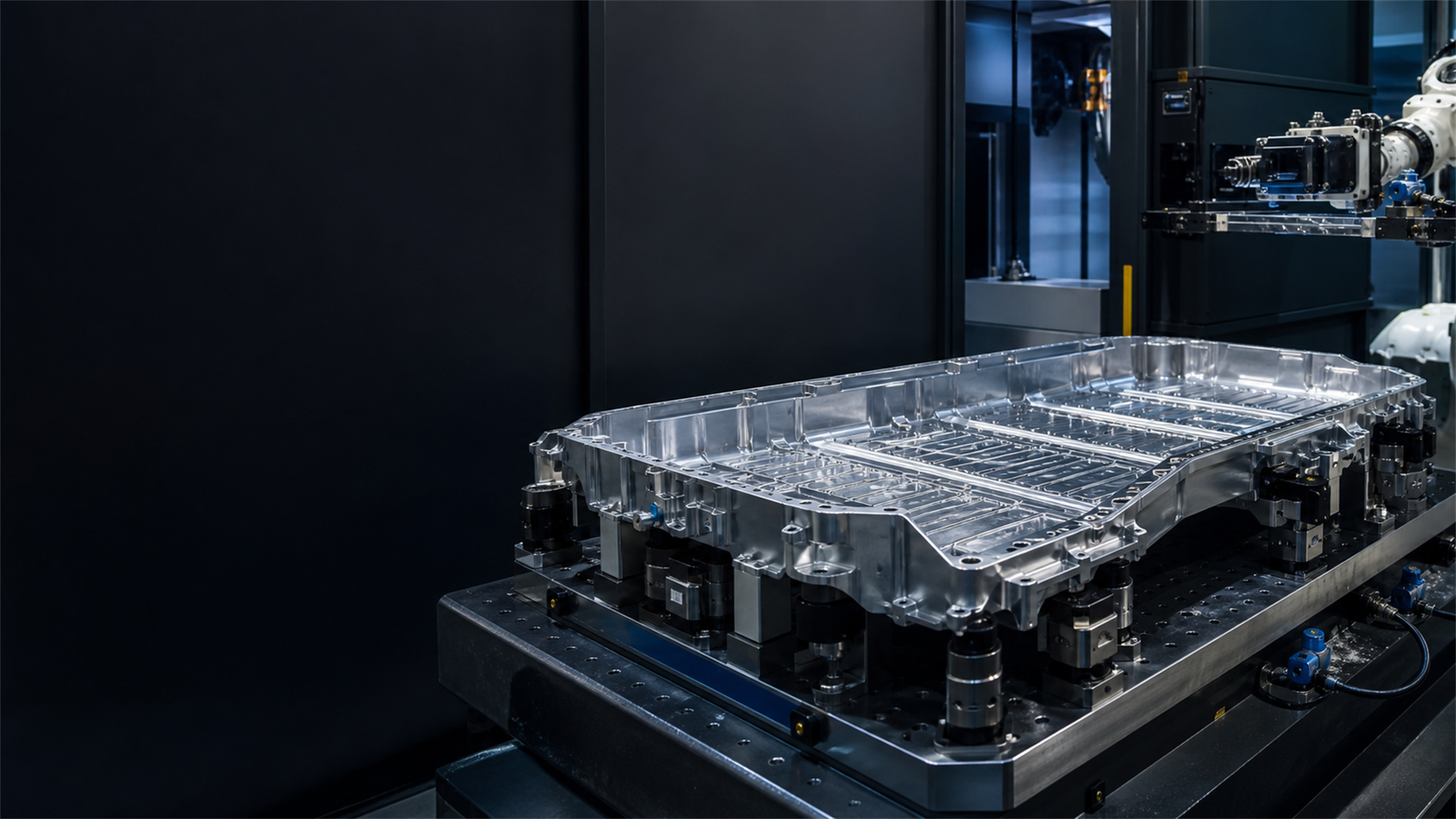
Battery trays, motor housings, and inverter housings are often large, thin, and easy to distort. Start with sound support and a stable machine interface. Add pallets or robots after cutting and inspection are proven.
What moves in the cut
An extrusion may arrive bowed or twisted. A die casting may carry uneven stock around bosses and thin walls. Cutting can release stress, and a long cycle adds heat.
Ask where the incoming part can be located and supported without bending. The answer depends on its condition, the cut order, related features, and the inspection datum.
Put support beneath cutting and clamp loads, but leave room for the tool, probe, coolant, and chips. A support that helps roughing may block a later feature.
Raw casting pads, trimmed extrusion ends, and finished holes do not offer the same references. State which features locate the first operation and how the datum moves after machining.
A pilot may be hand loaded; a later line may use pallets or a robot. Keep handling surfaces and service routes clear, then test loading and recovery.
Start at the machine table
A common machine interface can ease fixture exchange, but it cannot stop part distortion alone. Match the upper fixture to the part, then plan how it will move.
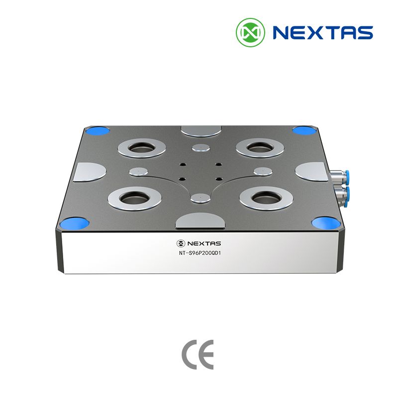
A practical machine-side route
A pneumatic zero-point plate can separate the machine interface from the part-specific fixture. This helps a pilot and later fixtures share one table connection.
When handling is the next bottleneck
When the part needs sequenced support
From pilot fixture to repeat production
Use a part that represents the real incoming condition. Run the planned cut order, cleaning routine, reload method, and inspection path. Record what moves and what stays stable before another fixture or station is ordered.
Show where the locators, supports, and clamps touch. Check those points against thin floors, sealing faces, bosses, and the tool path. Measure the unclamped part, the clamped part, and the released part where distortion matters.
Remove and reload the fixture with normal chips, coolant, lifting, and cleaning steps. The test should reveal trapped chips, difficult seating, awkward lifting points, or an operator check that is easy to miss.
Compare the part at the stages that matter to quality: incoming, rough machined, finish machined, unclamped, and inspected. Agree when the part must cool and which datum is used at each check.
Before automated loading, prove gripper clearance, part orientation, presence checks, clamp feedback, service routing, and the response to a stopped cycle. The complete cell still needs its own guarding, interlocks, and risk assessment.
What makes the quote useful
Identify usable raw pads, casting features, extrusion edges, and the finished features that must stay related. If the incoming shape varies, include that condition in the review.
Place support beneath the forces without hiding the surfaces that need machining, probing, cleaning, or inspection. Note where clamp marks or part movement are unacceptable.
State what is manual today and what may become palletized or robotic. That keeps handling access in the layout without pretending the untested cell is finished.
EV workholding questions
A die-cast housing may bring draft, porosity, and uneven stock. An extruded battery-tray rail may bring bow, twist, and variable cut length. The fixture must be based on the supplied part condition, not only the finished model.
Only if the part location, support, chip removal, inspection, and fault recovery are already understood. A manual or pilot setup can expose weak points before the same fixture idea is copied across a larger line.
Place support under the load path, keep clamps away from machined features, and review tool, spindle, probe, and chip-clearance envelopes together. The support layout should be checked with the real cutting sequence.
Prove repeat location, part presence, clamp-state feedback, service routing, clean seating, handling access, and recovery from a stopped cycle. These process checks do not replace the guarding, interlocks, and risk assessment for the complete cell.
Start with the part you actually receive
Send NEXTAS the model, incoming condition, cut sequence, machine limits, and inspection concern. We can compare a dedicated fixture, a zero-point base, and a later automation handoff around those facts.