Aluminum walls after roughing
Large pockets can release stock stress and remove the stiffness that existed at setup. Keep clamp contact away from finished walls, add support near the active cut, and check the part before and after unclamping.
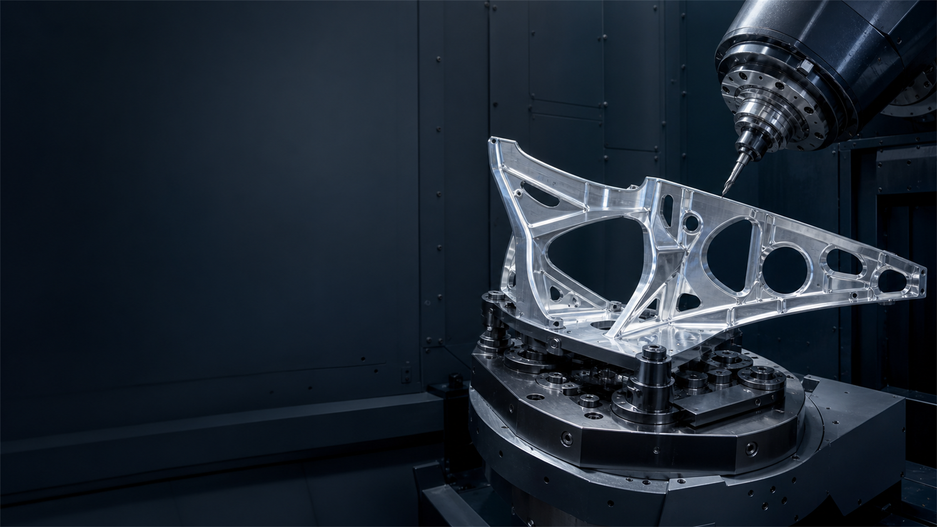
Aerospace / thin-wall 5-axis parts
A thin aluminum frame and a titanium bracket do not ask the same thing of a fixture. Start with the material, stock, cutting order, and surfaces the tool must reach. Then place the grip and support where they will not pull a finished wall out of shape.
Plan from the toolpath
A clamp can hold the stock and still spoil the part. Thin walls may move as pockets open. A long tool may clear the workpiece but strike a jaw, riser, or rotary table at tilt. The fixture review should follow the programmed faces in order: what is still stiff, what has become flexible, which datum remains, and where the toolholder travels. There is no useful universal clamp-force setting for that review.
Large pockets can release stock stress and remove the stiffness that existed at setup. Keep clamp contact away from finished walls, add support near the active cut, and check the part before and after unclamping.
Titanium may bring higher cutting load, heat, and chatter risk. Set support, overhang, grip feature, and roughing sequence from the actual toolpath rather than copying an aluminum setup.
The reference used for the first cut may disappear later. Plan how the part moves from roughing to finishing and CMM inspection while a measurable datum is still available.
Fixture route
A product name does not settle the setup. Compare grip height, prepared stock, toolholder sweep, part stiffness, rotary-table load, and the point at which the sacrificial material will be removed.
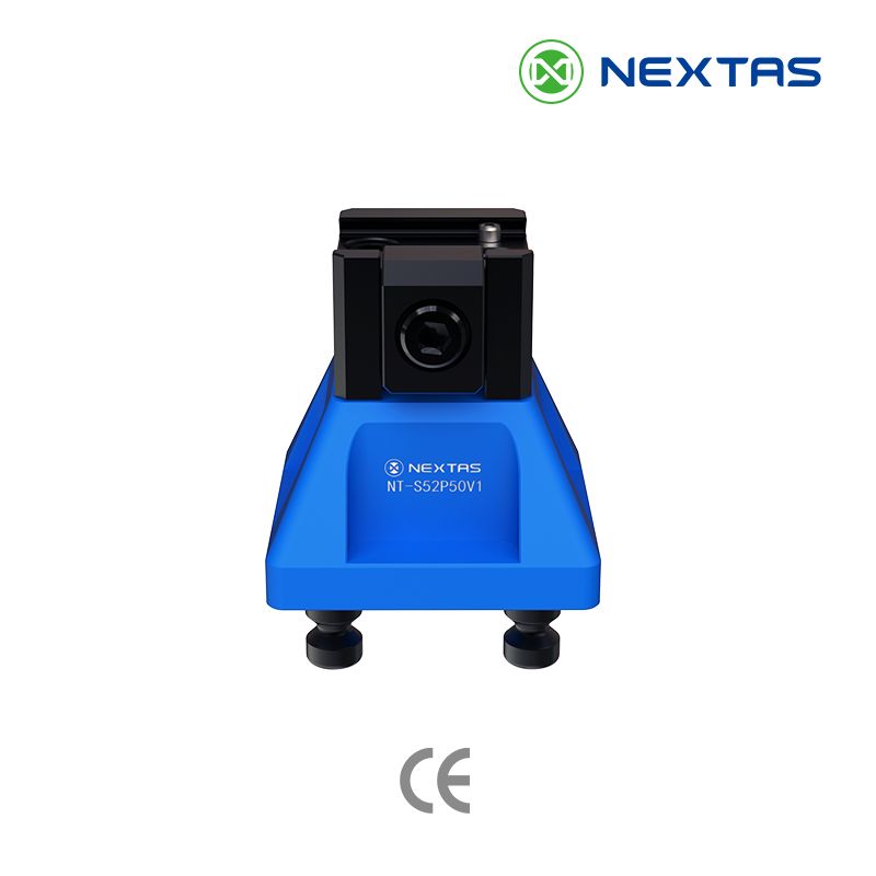
Low-grip starting point
A prepared sacrificial dovetail can keep the fixture body below much of the finished geometry. This can open several faces to the spindle without gripping a delicate wall. It only works when the stock can carry the grip and the cutter path, load, dovetail preparation, and final removal method have been reviewed together.
Transfer the fixture
Grip prismatic stock
Evidence before release
The drawing defines the target. The release plan shows whether the proposed grip, support, cutting order, and reload method can reach it on the buyer's machine.
Mark the faces removed at each stage, the wall sections that become flexible, and the datum available for the next setup. Put support where the part still has structure.
Check critical geometry in the free, clamped, and released states. Use the same contact points and clamp order planned for the trial part.
Simulate or dry-run the spindle, toolholder, cutter, jaws, fixture body, hoses, and table through every tilt used by the program.
Cut a representative part, reload it as production will, and inspect the named datums and walls. Record the clamp state, program revision, and inspection method with the result.
Start the engineering review
Mark the grip area, critical datums, thin walls, sacrificial stock, and faces that the spindle must reach in each operation.
Add the table interface, rotary travel, spindle and holder envelope, tool list, and any stack-height limit.
State which features will be inspected, in which clamp state, and whether the part must move between a machine and CMM.
Aerospace workholding FAQ
Put locating and clamp contact near stiff features, support the cut close to the load, and set the clamp order before roughing starts. Then compare the part in its free, clamped, and post-cut states. The result depends on the actual wall shape, stock, material, and toolpath.
It suits stock that can carry a prepared sacrificial grip below the finished geometry. That small grip can leave more faces open to the cutter. Check the dovetail preparation, cutting load, toolholder clearance, and removal plan on the actual part before release.
Not by default. Thin aluminum structures may move under clamp load as material is removed. Titanium parts can bring higher cutting load, heat, and chatter risk. Use the material, stock condition, wall layout, cutter path, and inspection result to set support and clamp force.
Use a representative trial cut, a documented reload check, and inspection of the critical datums and walls. CMM results are useful when they follow the same clamp state and operation order planned for production. Record the method, not only the final number.
A drawing starts the review
Send the four inputs above. NEXTAS can compare the grip, support, transfer, and inspection route around your actual setup.