Deflection after release
A thin titanium wall or PEEK feature may measure differently once clamp load is removed. Plan support close to the cutting force and include a released-part check.
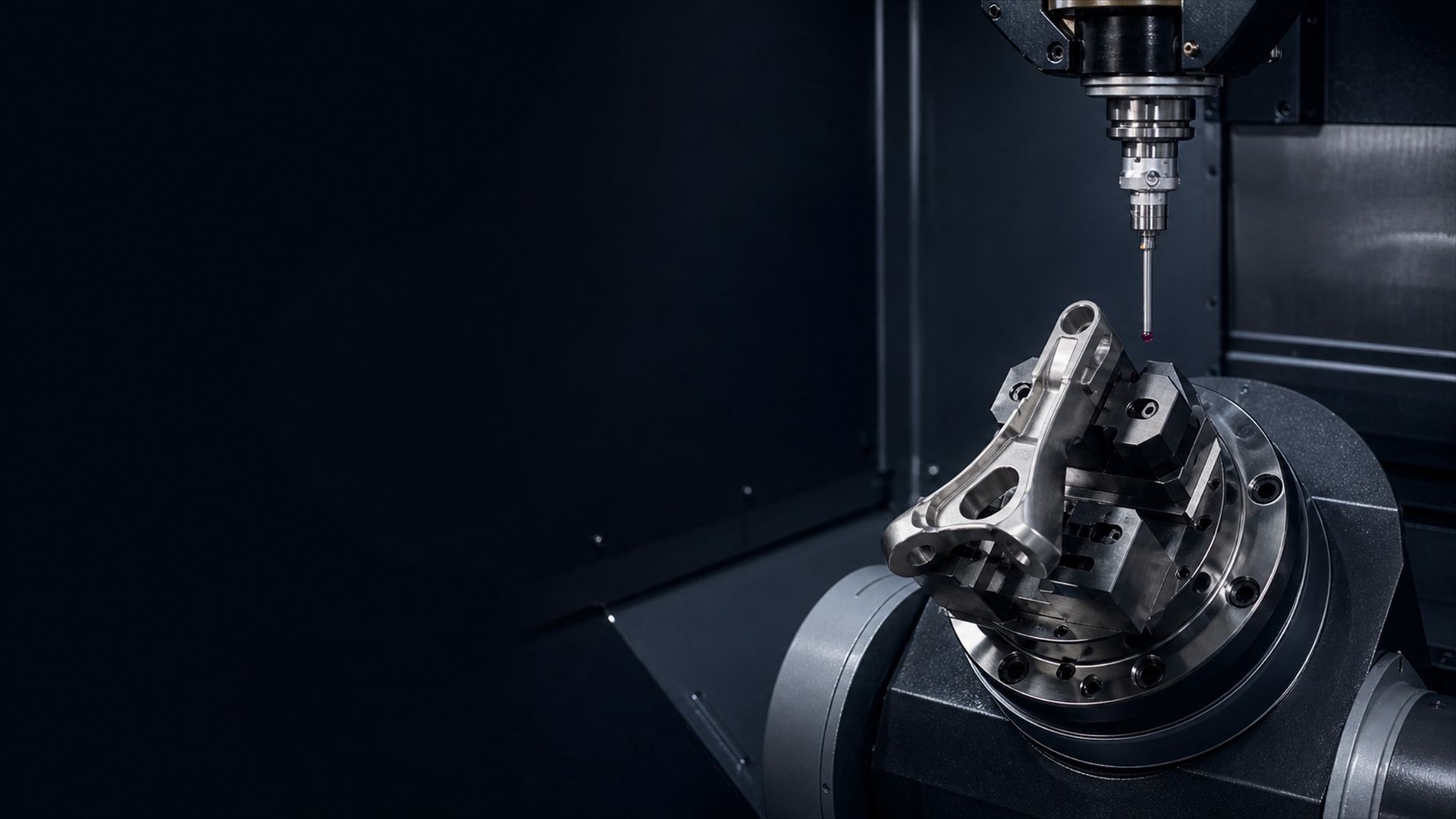
Medical CNC machining / small-part contact
Titanium, stainless steel and PEEK parts can be thin, short and difficult to support. Start with the surfaces you may touch, then choose the jaws, support and inspection plan.
Start at the drawing
A small part offers little room for jaws, supports, cutters and gauges. The drawing should show protected faces, critical relationships and the condition in which each feature is inspected. That prevents a neat-looking setup from loading the wrong wall or covering an edge that still needs deburring.
A thin titanium wall or PEEK feature may measure differently once clamp load is removed. Plan support close to the cutting force and include a released-part check.
A sharp jaw edge or one trapped chip can damage a finished surface. Define jaw material, contact width, cleaning method and the surface acceptance check.
Leave room to inspect edges, remove burrs and reach the datum features. If the fixture hides these areas, the process needs a planned second position or another holding route.
Choose the contact method
Part shape, wall stiffness and permitted contact decide the route. A product name alone cannot tell you whether the part will stay flat or come out without marks.
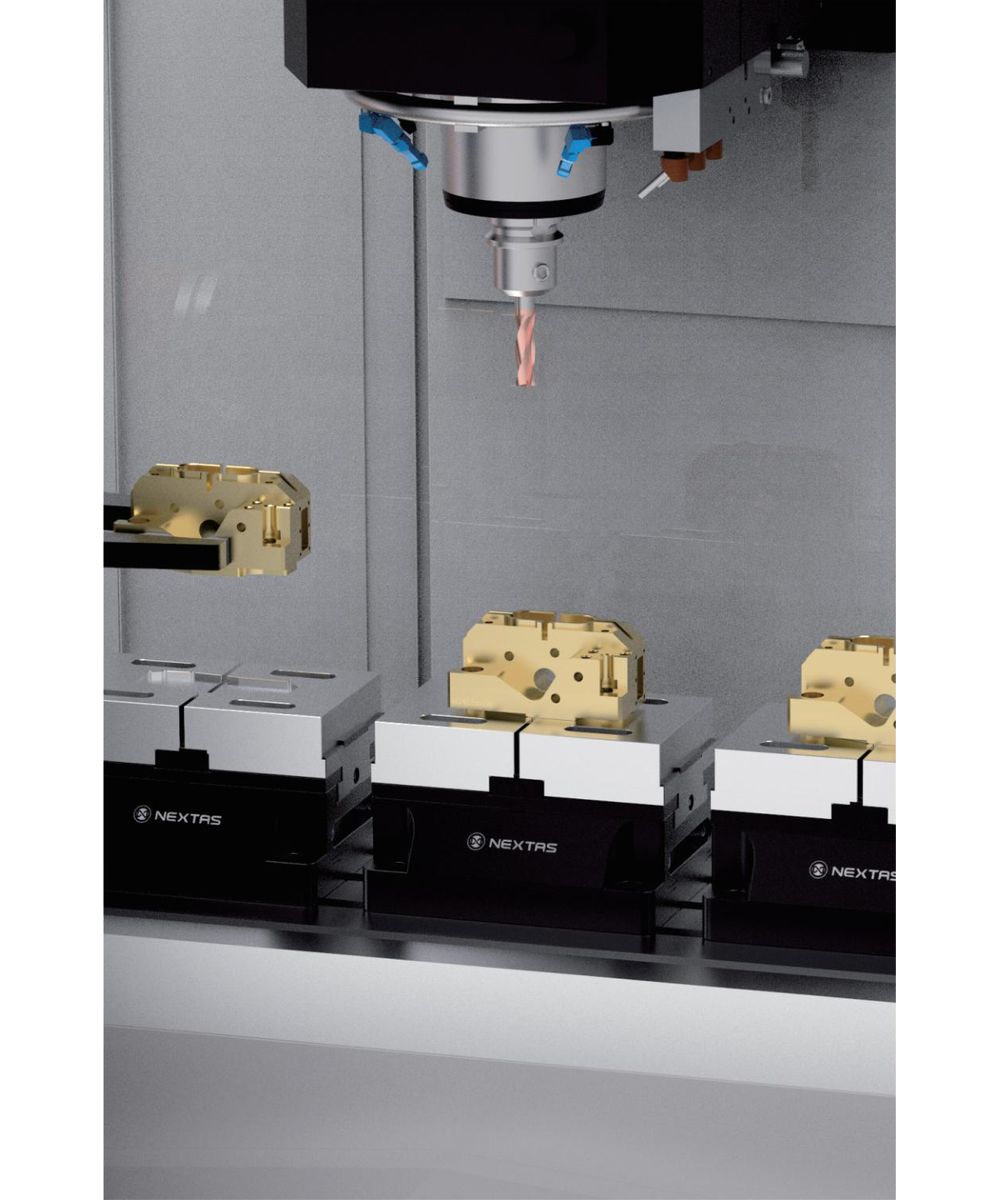
Route for small prismatic parts
A self-centering vise can keep a small prismatic blank near the spindle center as part width changes. For a finished or thin-wall part, the important work is in the jaw contact: soft jaws, pads or a custom nest must spread load without covering the cutter or gauge path.
Route for open tool access
Route for process transfer
First-piece evidence
Use the drawing and quality plan to choose the checks. Keep the fixture revision, jaw revision and result together so the evidence follows the setup.
Before cutting, inspect the incoming blank, protected surfaces and key free-state dimensions. Photograph unusual contact areas and note any existing marks or burrs.
Load a real part or representative blank. Check full seating, jaw contact, support location, tool clearance and whether the loading method can trap a chip.
Inspect critical dimensions and form after release, not only in the fixture. Repeat the load and release cycle enough times for the customer’s sampling plan.
Confirm edge access, the agreed cleaning state, part identification and the inspection record required at handoff. These needs can change jaw material and fixture access.
Drawing review
Identify faces that may be clamped, faces that must stay mark-free and features that must remain open for tools or gauges.
State whether the part is rough, semi-finished or finished when loaded, plus the material, previous operation and next inspection step.
List the released-part dimensions, surface check, burr check, cleaning state and traceability record needed before the fixture is approved.
Medical workholding FAQ
Start with the surfaces that may be touched. Use broad, part-shaped contact where possible, support the wall near the cutting load, and control the clamping input. Inspect the contact area and measure the part again after release because a dimension taken only while clamped can hide elastic movement.
PEEK is less stiff than titanium or stainless steel and is more sensitive to point load and heat. Use wider contact, avoid sharp jaw edges, limit unsupported length, and review coolant, cleaning and drying conditions against the customer's process. Confirm the setup with an actual part or representative blank.
Check whether the jaws or supports block deburring and edge inspection. On the first piece, inspect critical edges and protected surfaces, then measure key features after unclamping. Record the fixture, jaw and program revision so a later result can be traced to the setup that produced it.
State the required incoming and outgoing cleanliness condition, restricted contact materials, approved cleaning method, protected surfaces, part identification method and inspection record needed. NEXTAS can use those inputs to shape the workholding proposal, while the customer remains responsible for its regulatory and quality-system approval.
Start with one real part
Mark the protected surfaces and tell us how the released part will be inspected. NEXTAS will compare the practical holding routes.