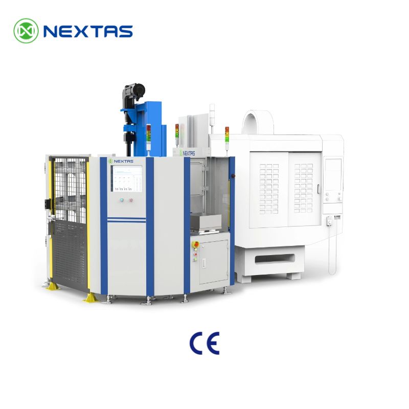
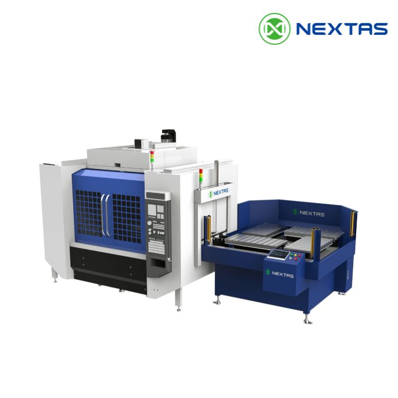
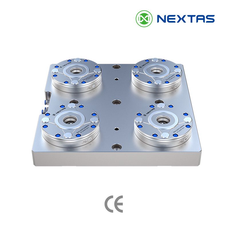
Equipment and buffer map
Locate each machine, pallet or part buffer, handling unit and manual load point; record travel paths and the states available to FMS.
A production management platform for configured schedules, connected machine data, traceable records and live dashboards across one cell or a larger line.
Use one agreed scope to plan work, view connected equipment states and link production records. Existing ERP, MES, PLC and automation-control roles must be mapped before integration; FMS does not replace them by default.
FMS is the software and control layer. Cells, robots and pallet magazines are separate hardware scope. Fit depends on the exact controllers, protocols, I/O, firmware, network and handshake list, including projects that use the NEXTAS Automation Series.
FMS ROLLOUT DECISION
Choose by the coordination problem and validated interfaces—not by a fixed machine count. Start with the smallest accepted scope, then add modules as data and handshakes are verified.
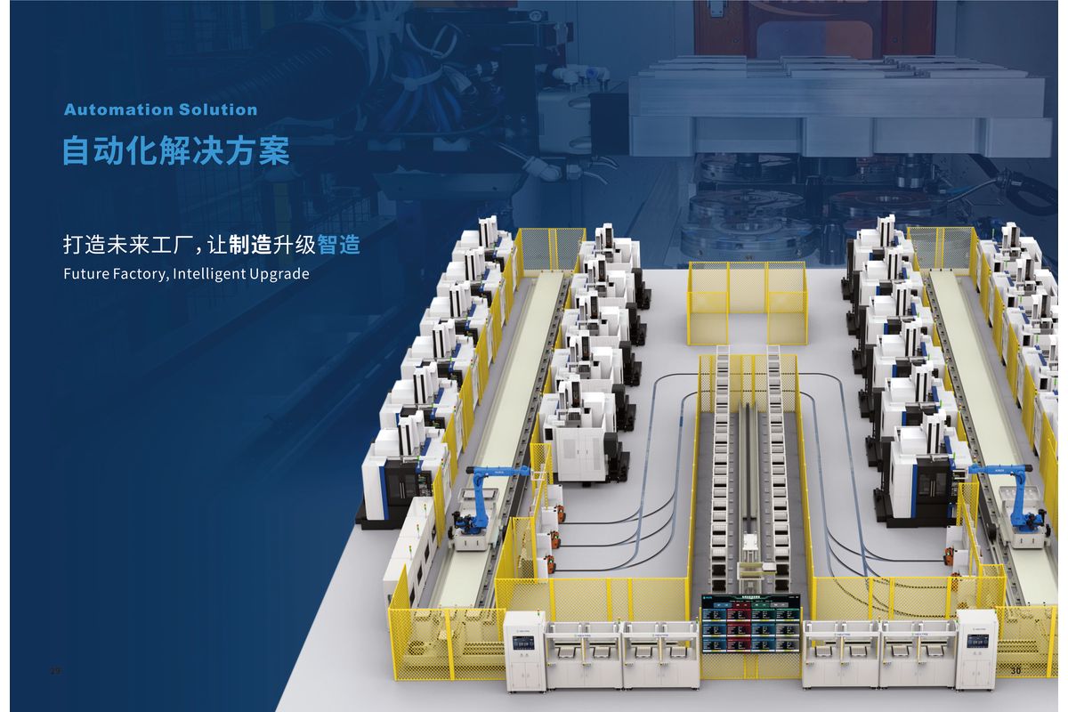
45-second system overview
This overview shows the physical production context—CNC machines, robotic handling, and coordinated cell flow. Software modules, interfaces, and acceptance criteria are detailed below and defined for each site.
Review the 8 modulesEach module covers one part of production management. Enabled modules, connected data and handoffs are fixed in the project scope.
Configurable view of the production progress, process steps, orders and equipment states supplied by connected sources.
Can receive approved ERP/MES order fields and create schedules from configured priority and queue rules.
Records completed, in-process, queued and exception states when the required order fields and state updates are available.
Displays available machine states and linked tool, fixture or process-version records from the mapped data sources.
Links configured tool positions and life fields, then issues change prompts according to the approved rules and source data.
Fixture-to-pallet/datum configuration, positioning and clamping confirmation, repeatability logging with a project-defined sample size and acceptance plan.
Uses the selected cameras, lighting, model and thresholds to check agreed features. Detection performance requires representative samples and an acceptance plan.
Calculates configured uptime, downtime, load and efficiency fields from connected state data and agreed downtime codes.
The workflow can link product setup, approved ERP/MES fields and FMS execution. Traceability covers only the mapped data and verified interfaces in the accepted project scope.
Product Configuration
Machine program, tool list, fixture type, cycle time and quality checkpoints are defined in the system.
ERP/MES Link
Approved material, quantity, due-date and priority fields can pass from ERP/MES after mapping and interface tests.
Schedule Generation
FMS can generate a schedule from the configured machine, tool, order-priority and exception rules.
Real-time Execution
Approved equipment can receive configured commands and return the states made available by its interface.
Quality & Traceability
The selected vision setup records inspection output. Pass or fail authority follows the approved inspection and acceptance plan.
Data Close
Approved production, tool and inspection fields can return to ERP after the data map and write-back rules are tested.
The four layers separate display, scheduling, execution interfaces and communication. Expanding from one cell to more equipment requires an approved interface map, licenses, network capacity and renewed acceptance checks.
Shows the states, orders and progress fields available through the approved machine and business-system interfaces.
Applies the approved priority, load, routing and exception rules to propose what connected equipment should do next.
Sends configured commands and reads available states from approved machine, handling and storage interfaces.
Can use OPC UA, Profinet, EtherCAT, Modbus or another agreed method. Device implementation, data fields and handshake behavior must be confirmed for the project.
Confirm machine interfaces, scheduling rules, data ownership, network limits and acceptance tests before the module and rollout scope is accepted. For the interface list and handover checks, use the FMS scope and acceptance guide.
Choose the phase order from the site's approved interfaces, operational need and test plan:
Connect approved state data to the dashboard before adding scheduling.
Add production planning and order sequencing after priority and exception rules are accepted.
Add tool and fixture records after their source fields and alert rules are mapped.
Add the validated vision task and the traceability fields included in the accepted data map.
FMS LAYOUT PLANNING
Use these planning inputs to define the engineering review. They are not a customer deployment, installed-performance record or substitute for site validation.
Locate each machine, pallet or part buffer, handling unit and manual load point; record travel paths and the states available to FMS.
Separate safeguarding, access, fault-recovery and manual-intervention responsibilities. FMS coordination does not replace the complete cell risk assessment.
Confirm power, air, network, controller, I/O and protocol connection points together with cable routes, ownership and handshake tests.
Reserve access for maintenance, calibration, replenishment and recovery, plus any future equipment that is included in the approved expansion boundary.
A project review should return a scaled concept layout, equipment and interface list, open-risk log, ownership map and acceptance boundary for the selected site—not a generic plant template.
BUSINESS-CASE INPUTS
Calculate from the current site's measured baseline and a validated operating scenario. This page does not guarantee savings, productivity gains or payback time.
Record part mix, batch size, changeover, staffed and unstaffed hours, stoppages, scrap handling and the present planning workload.
Use only the machine states, scheduling rules, recovery method and unattended operation that the interface and acceptance plan can support.
Include software, controls, licenses, integration, training, validation, infrastructure, maintenance and recurring support—not only equipment purchase.
Test conservative and base scenarios for demand, availability, ramp-up, exceptions and contingency before the business case is approved.
Decision boundary: compare scenarios only after the site baseline, interface scope and acceptance assumptions are documented. No universal ROI or site-independent payback claim is made.
The Automation Series covers physical hardware — vault cells, rotary warehouses, truss units. The FMS System is the software and control platform that coordinates scheduling, traceability, tool management and production visibility across those physical units.
Controller, I/O, PLC, protocol, firmware, and handshake compatibility must be confirmed for the exact machine and project signal list. The website does not make a blanket compatibility claim for controller or CNC brands.
Consider FMS when several machines or handling units need a shared schedule or common production records. Confirm controller, I/O, network, safety-system roles and fault recovery before using the software in an unattended cell.
Yes. Each phase needs a written module scope, data owner, interface test and acceptance method. The factory does not have to implement all 8 modules at once.
An FMS schedule follows the modules you turn on, the machine and controller interfaces, the protocols and data you already keep, the layout, the rollout phase, training, and acceptance. Milestones go in the quotation after that scope is reviewed. This page does not state an implementation duration.
The agreed FMS handoff may include the architecture and interface map, protocol or data-source scope, acceptance records, training scope, and recovery responsibilities. The quotation or order confirmation defines the exact deliverables; the website does not promise the same document package for every implementation.
Fast quote
Name, work email, and what the cell has to schedule are enough to start. We'll scope the software and a price after we see the controllers and the data you already keep.