
The short answer: test the claim you need
Repeatability means how closely a result returns when the same action is repeated. It is not the same as accuracy. Accuracy asks how close a result is to a chosen true or accepted value. In this article, 0.003 mm equals 3 micrometres. A micrometre is one thousandth of a millimetre.
When a catalog lists <0.003 mm repeat positioning, ask what was removed and reseated. Ask where it returned. Note the measured direction and test used. The value may cover a matched carrier and receiver interface. It does not cover every part, pallet, machine, station, and inspection step above that interface.
Start with a written question. “Can this carrier return to this receiver?” is one question. “Can it move between two machines?” is another. “Can the finished bore hold its drawing tolerance after transfer?” is a third. Do not blend the results.
Four claims need four evidence boundaries
| Claim | What changes | What the result may support |
|---|---|---|
| Same-interface reseating | One carrier is released and reseated on one receiver | Return of that interface and test reference |
| Cross-station transfer | The carrier moves between named receivers | The combined station-to-station result |
| Finished-part result | A controlled cut and part inspection are added | The tested process and named drawing features |
| Measurement confidence | The reference, instrument, routine, and uncertainty are qualified | Whether the observed result supports the decision |
A small same-seat range can be real. Cross-station transfer may still be poor. A stable transfer can yield a bad part. Tool wear, heat, part support, or cutting force may dominate.
What the current NEXTAS product pages state
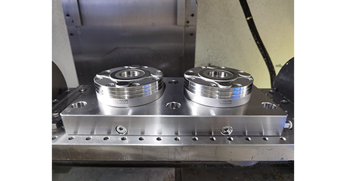
The current NEXTAS MFG page lists these V1 receivers at repeat positioning of ≤0.003 mm. It also lists a clamping-force field for each model. BDS has its own product page and a different interface family.
| Named receiver | Listed repeat positioning | Listed clamping-force field |
|---|---|---|
| NT-S200P85V1 | ≤0.003 mm | 4 kN |
| NT-S200P120V1 | ≤0.003 mm | 12 kN |
| NT-S200P160V1 | ≤0.003 mm | 18 kN |
| NT-S200P195V1 | ≤0.003 mm | 40 kN |
| BDS A024 and B024 datum bodies | <0.003 mm | 60,000 N |
These values belong to the named product fields and their controlled source. They are not an allowable cutting-force result. They are not a safe weight limit. They do not prove the full stack. Confirm the current drawing and quotation for the selected model. Check the carrier, studs, release method, mounting pattern, and inspection scope. Do not mix MFG and BDS parts because their pages show a similar repeat value.
Write the test rule before touching the hardware
Name the receiver, carrier, pallet, and adapter. Name the fixture, reference, machine, station, and test direction. State which items stay fixed. State which item will be removed. Say whether offsets may remain active. Write the buyer’s pass rule, units, and sample plan. Set the rule for an invalid event before data collection begins.
There is no universal repeat count or shop-floor pass limit. A development check, production release, machine acceptance, and regulated part process do not carry the same risk. The owner of the requirement must choose a plan that fits the decision. Changing the count or limit after seeing the data weakens the evidence.
Keep an identity ledger. This is a list of each physical item and its serial or asset number. It prevents a “same setup” test from quietly changing a receiver, carrier, stud, adapter, fixture, gauge, or software routine.
Separate display resolution from measurement uncertainty
A probe or indicator may display very small steps. Display resolution does not show how much doubt surrounds the answer. Measurement uncertainty is the estimated doubt around a measured result. It includes the reference, instrument, mount, and probe direction. It also includes the routine, shop state, data handling, and operator effects.
If uncertainty is large beside the acceptance band, the test may not separate a pass from a fail. Qualify the instrument and reference for the direction being measured. Check that the routine does not reset or learn away the movement. Record raw signed values, not only rounded ranges or a green status.
State where the reference sits. A feature close to the interface may show interface motion. A tall test bar can show angular change as a larger linear shift. Both can be useful, but they are not the same test.
Prepare the interface without changing the test
Follow the machine and product instructions for safe release, cleaning, and reseating. Control stored pneumatic, hydraulic, spring, and gravity energy. Normal pressure, a seat signal, or a PLC bit is a process signal. It is not safety-rated proof unless the full safety function was designed and validated for that use.
Inspect only the mating faces and studs you can reach. Check fasteners, direction marks, and the mount. Use the maker-approved cleaning method. Do not invent a cleaning pressure, lubricant, torque, or warm-up rule. Record the machine and shop state instead. If a contact is damaged, stop. If the clamp state is not clear, stop and seek model-specific review.
Before the first release, measure the fixed reference without reseating. This short stability check helps show whether the machine and measurement routine move on their own. It does not replace the reseat test.

Run a same-interface reseat test
- Confirm identities, the reference, direction, safe release state, measurement routine, and written acceptance rule.
- Measure the seated reference. Store the raw signed value with its unit and event number.
- Release and remove the carrier by the approved method. Do not alter the receiver mount or work offset.
- Inspect and clean accessible contacts only as the approved method allows. Log anything found.
- Reseat and clamp in the same approved way. Confirm the normal process state without treating it as safety proof.
- Measure the same point and direction. Keep valid events and note any stopped or invalid event.
Keep the low and high values. Keep the signed range, center shift, order, and raw event list. A trend across event order may matter even when the range looks small. If an operator must push, tap, or turn the carrier to get a good value, that act belongs in the result.
Add a separate cross-station transfer test
Identify every receiver and its machine coordinate system. Keep carrier direction and the measured reference clear. Move the same carrier through the planned route. Do not apply a fresh station offset after each move unless the claim includes that step. If compensation is allowed, report uncorrected and corrected results apart.
Cross-station error can include the receiver mount and station shape. It can include machine return, coordinate rules, carrier index, and test differences. Do not report it as the repeatability of one receiver. If several carriers must swap, test the gap from one carrier to the next.
Prove the finished part with a controlled trial
An indicator result is not a finished-part result. Use an approved trial with the intended part, fixture, jaws or supports, tool path, cutting load, offsets, coolant state, and inspection method. Choose drawing features that reveal transfer effects and features that reveal the cutting process.
Keep each part tied to its station, carrier, cycle, tool, and raw interface data. The interface may be stable while parts drift. If so, check machine shape and tool wear. Check heat, part bend, support, cutting force, offsets, and inspection.
Process capability needs representative production data and a stable process. A short reseat test cannot prove it. A catalog value also cannot prove safe holding. Fixture strength, loads, workpiece shape, support, and failure effects require an engineering review.

Read the pattern before deciding
| Data pattern | Layer to examine | Next evidence |
|---|---|---|
| Fixed reference moves before a reseat | Machine or measurement stability | Check the reference, machine state, and routine |
| One receiver is stable and another is shifted | Station mount or coordinate chain | Compare receiver mounting and station references |
| One carrier differs from the others | Carrier, studs, adapter, or handling | Run a planned carrier comparison |
| Interface is stable and finished parts drift | Machining and inspection stack | Link tool, heat, support, load, offsets, and part data |
| Result is close to the limit | Decision confidence | Review uncertainty and the acceptance rule |
Use this shop test card
- Use this card before the run. Name the claim. Name the one item that will move. Name all parts that must stay put.
- Mark each base and each part. Use the same names in the data sheet.
- Make the machine safe. Keep hands out of a live clamp. Stop if the clamp state is not clear. Stop if a face has a nick or dent. Stop if the mount is loose.
- Do not force a part to seat. Do not tap it to get a good read. Do not hide a shift with a new zero. Take a base read. Save it.
- Let go of the part as the work rule says. Lift it by the safe method. Check the faces that you can see. Clean them as the maker says.
- Put the same part back. Use the same side and the same turn. Lock it as the maker says. Check the normal seat state. Do not call that a safe state on its own.
- Read the same point. Save the sign as well as the size. Add the time and event ID. Keep each good test event.
- Mark a bad test event. Say why it was bad. Do not erase a poor but valid read. Look for a trend in the test order.
- If the base test fails, stop. If the part test fails, check the cut and the part. Get the test owner to sign the rule.
- Keep the raw data with the report. State what the test did prove. State what it did not prove. Use that line in the quote and the buy-off.
Build an evidence pack a buyer can review
Include the model and controlled drawing. List the interface IDs, carrier, fixture stack, and station map. Show the reference shape and test directions. Add the safe handling method and pass rule. Keep the sample plan, tool status, doubt statement, shop notes, and raw signed values. Add photos of the setup, not just one good reading.
State the conclusion at the same boundary as the test. Say “this carrier reseated on this receiver within the stated rule during this test.” Do not widen that conclusion to the full system. List what was not tested, such as other carriers, other stations, cutting, long-term wear, or finished parts.
For an engineering review, send part and fixture mass. Send the loads, machine table, mount, and release source. Add the route, interface claim, part limits, test plan, and needed records. This helps match the hardware and proof before an order.
Zero-point repeatability test FAQ
What does <0.003 mm mean in this article?
It means less than 0.003 millimetres, or less than 3 micrometres. Here it refers only to the repeat-positioning field for the named interface. The current drawing, quotation, test method, and selected model control the actual product claim.
Is same-interface reseating the same as cross-station transfer?
No. Same-interface reseating returns one carrier to one receiver. Cross-station transfer moves it to another receiver and adds station mounting, station coordinates, carrier direction, and other interfaces to the result.
How many reseat cycles should I run?
There is no universal count. Choose and record the sample plan before the test based on part risk, buyer requirements, expected use, and the quality system. Keep every valid event and explain any excluded event.
Does a probe with fine resolution make the result reliable?
No. Resolution is the smallest displayed step. Measurement uncertainty is the doubt around the full result, including the reference, instrument, setup, routine, environment, and operator. Qualify the measurement process for the decision.
Does a catalog repeat-positioning value guarantee finished-part tolerance?
No. Finished-part results also include the machine, station mount, pallet, fixture, jaws, workpiece, cutting load, tool, heat, offsets, and inspection process. Prove the complete process with a controlled trial and part inspection.
What should I send for a repeatability test review?
Send the selected model and current drawing, receiver and carrier identities, machine and station details, pallet and fixture stack, reference feature, measurement plan, raw signed data, environmental notes, and the buyer's acceptance rule.
Need a review of your repeatability claim?
Send the interface, stack drawing, station route, reference, raw data, and buyer rule. NEXTAS can help separate product facts from process proof.
Request an engineering review