“Can we keep our AMF pull studs and replace only the receivers?” That is usually the first commercial question behind an AMF zero-point alternative. It is also a question that cannot be answered from “size 20,” a photograph or one nominal diameter.
A pull stud can enter a receiver and still be wrong. It may sit high, contact on the wrong surface, bind as the pallet warms, trap chips where you cannot see them or release differently after a loaded cut. In an automated cell, the hardware may clamp while the new sensor logic leaves the robot waiting for a state it will never receive.
So this is not a brand-versus-brand scorecard. It is a practical way to decide what stays, what changes and what has to be proven before a purchase order becomes a fleet conversion.
What are you unwilling to rework?
Before comparing modules, walk the job from the pallet rack to the PLC cabinet. Which items are already qualified and expensive to disturb? The answer may include the pallet bodies, stud mounting, fixture stack height, machine subplate, programs, probing routine, robot gripper, air or hydraulic services and spare-parts policy.
Write those constraints at the top of the RFQ. “Replace the modules” is too vague. A supplier reading that line does not know whether a two-millimeter stack-height change is acceptable, whether the existing pull studs are protected assets or whether changing a connector would trigger new machine validation.
Three routes—and where each one makes sense
| Route | What stays | Why buyers consider it | Where the work moves |
|---|---|---|---|
| A. Keep the existing studs | AMF-equipped pallets and fixtures | Avoids immediate work across the pallet fleet | The new receiver must be proven against every installed stud variant |
| B. Keep the pallets, change the studs | Pallet bodies and upper workholding | Can let the buyer source a documented stud-receiver pair from one supplier | Each mounting position needs access, conversion, inspection and requalification |
| C. Use a parallel standard | Current AMF cells remain unchanged | Isolates legacy-interface risk from a new machine or program | The shop carries two standards, two spare strategies and clear identification rules |
Use one simple rule: the more old hardware you retain at the mating interface, the more evidence you need before production. Route A is not the conservative choice if the installed part numbers and drawings are missing. In that situation, it may be the route with the most unknowns.
Route B often looks intrusive on paper, yet it can be easier to document when the studs are accessible and the pallet count is modest. Route C deserves serious consideration when the purchase is for a new cell that does not need to share pallets with the old one. These are starting points, not universal answers.
“Size 20” is not the interface
AMF's own product pages show the problem. The BM20 mechanical module 562354 uses a size 20 M12 arrangement. The KP20 pneumatic flange module 423988 points to a specific M16 pull stud. Same nominal size, different engagement thread.
AMF also publishes model-specific force, pressure and repeatability conditions for those modules. They are not NEXTAS equivalence claims. The point is simpler: a family label helps you find a product range; it does not define the mating geometry.
Make one row for every pull-stud position on every pallet type. Record the module and stud order numbers, stud role, thread, collar form, seating height, drawing revision and pallet coordinates. Add the timing direction and approved measurements where drawings are unavailable. If a field is unknown, write “unknown.” Do not copy a value from the next pallet because the parts look alike.
Map the datum before matching part numbers
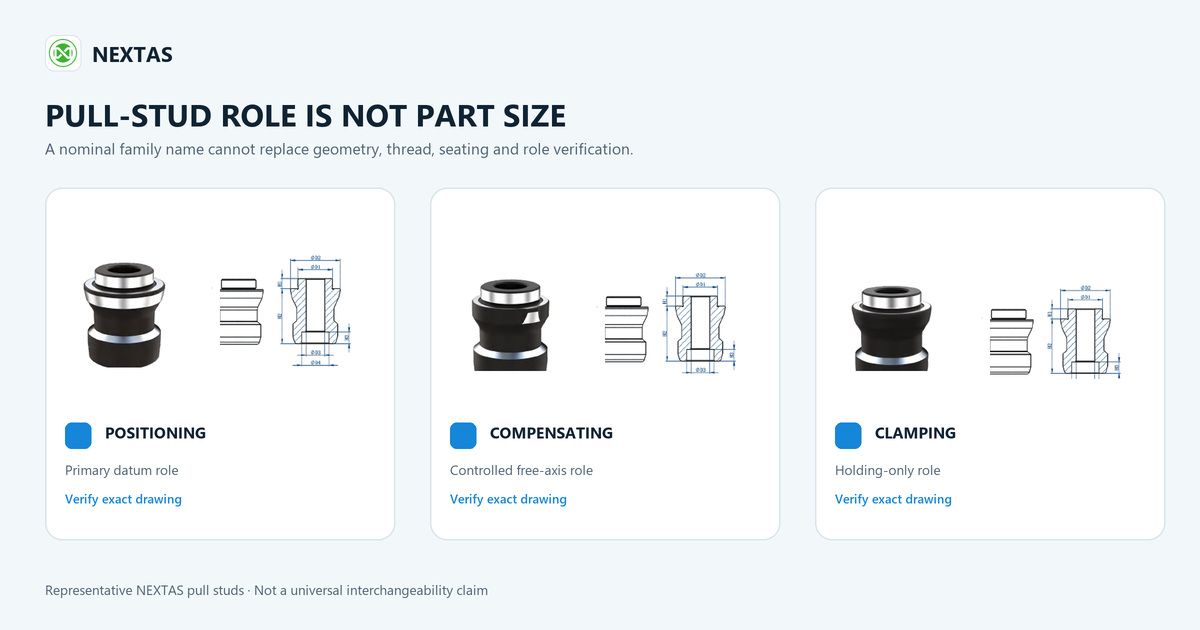
A pallet with three or four studs does not necessarily have three or four identical locating points. AMF's official zero-point systems catalog describes different jobs within a typical arrangement: a zero-point stud establishes the primary reference, a timing stud compensates along a free axis and an undersize stud adds holding without creating another full locating constraint.
Suppliers may use different names, but the locating function still has to be preserved. Mark each position on the pallet underside drawing and show the intended compensation direction. If the quotation proposes one stud geometry for every position, ask the supplier to explain the resulting datum scheme rather than accepting “same size” as the answer.
Fit is not proof of seating or release
A clean bench insertion tells you only that the stud can enter the receiver. It says nothing yet about full seating, pull-down travel, chip evacuation or release after a loaded cut.
Start with the mechanical stack. Ask where the pallet seats, which surfaces capture the stud and how the proposed stack height compares with the current machine offsets. Give the supplier the fixture mass, center of gravity, cutting forces and moments. Holding force is not pull-in/locking force; the quotation should label both and state which value was used for the load check.
Then check the operating medium at the module. AMF publishes mechanical, pneumatic and hydraulic products with model-specific requirements. The KH20 hydraulic surface-mounted module, for example, uses hydraulic opening and provides an optional pneumatic connection for blow-out and support control. That does not mean another module will use the same pressure, timing or port arrangement. For a pneumatic installation, the pressure shown at the plant header is not necessarily the pressure at the furthest module while several units release. Measure the worst branch dynamically.
For automation, invite the controls engineer into the RFQ. Which signal does the robot wait for: open, clamped, pallet present or all three? What happens if pressure drops halfway through a change? How does the cell recover after an interrupted cycle? A receiver is not a drop-in replacement if a missing hardware state has to be disguised in software.
Ask the supplier to label what has actually been proven
“Compatible” is too broad to stand on its own. Require one of four statuses: drawing reviewed, sample measured, pilot passed or released for production. They are not synonyms.
The reply should name the drawing revision, physical sample, stud role, proposed receiver and remaining exclusions. If a quote says only “AMF size 20 compatible,” send it back for a part-number-level answer. A careful list of open items is more useful than a confident sentence with no evidence behind it.
What to put in the first email
You do not need a perfect specification before talking to a supplier. You do need enough information to expose the unknowns. Four attachments are usually more useful than a long free-form message:
- Interface file: the completed position sheet from above, pallet underside drawing and photographs of readable markings.
- Machine conditions: table model, fixture mass and center of gravity, representative forces and moments, contamination, duty cycle, operating medium and pressure.
- Controls schedule: required states, connector information, PLC sequence, blow-off timing and recovery behavior.
- Acceptance sheet: process tolerance, repeat-location method, cutting trial, sample quantity and the person authorized to release the configuration.
If a part number or dimension is missing, say so. The right next step may be a drawing request, an approved sample measurement or a pallet survey—not a speculative cross-reference.
Make the pilot the purchase gate
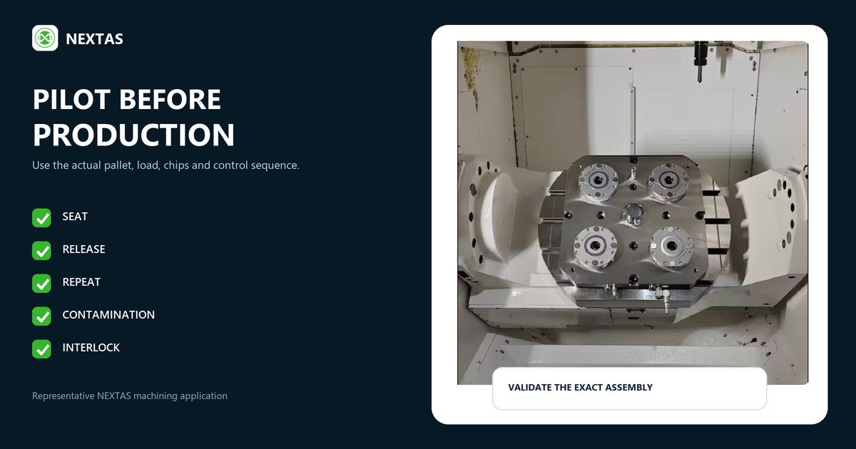
Treat the pilot as the point where the fleet order is earned, not as a demonstration after it has already been placed. Use the real pallet layout, a representative fixture and the normal chip, coolant and automation conditions. Agree on the pass criteria first.
| Stage | Question to answer | Evidence to keep |
|---|---|---|
| Drawing review | Do the role, thread, collar, seating height, layout and release travel agree? | Signed interface drawing and part-number cross-reference |
| Static assembly | Does the pallet seat and release fully without interference? | Measured seating and inspection record |
| Repeated loading | Is location stable over an agreed sample? | Results against the process error budget |
| Shop exposure | What changes with chips, coolant, temperature and normal handling? | Dirty-condition and recovery results |
| Cut and automation | Does it hold, release and report the right states in the real cycle? | Approved part result and sequence sign-off |
Set the location limit from the part's error budget. A catalog repeatability figure is not an acceptance plan. For example, if the part has a tight positional tolerance, measure the current process baseline and decide how much error is available to the pallet interface after probing, spindle, fixture and toolpath effects are considered. Do not assign the entire part tolerance to one catalog number.
Count cost per pallet, not per module
Put each route into four cost buckets: one-off engineering, cost per converted pallet, cost per machine and recurring spares or training. Then add the exposure of one interrupted production cell. Include that exposure explicitly; it may outweigh a small difference in receiver price.
- Route A: include dimensional review, sample measurement, receiver engineering and the most demanding validation program.
- Route B: multiply stud replacement, access, cleaning, torque control, inspection and requalification by the real pallet count.
- Route C: include separate spare stock, permanent identification, work instructions and the risk of an operator mixing standards.
Run the comparison at three scales: one pilot, the first production cell and the full fleet. A solution can be inexpensive at the pilot stage and still become the costly choice when dozens of pallets need work.
If two standards will coexist, identify the receivers, studs, pallets and storage locations permanently. Update the BOM and spare list. Make it clear who may approve a substitution. This is ordinary shop discipline, but it is what keeps a successful trial from turning into an uncontrolled mix on the shop floor.
Three phrases worth challenging before the PO
“It is the same size.” Ask for the thread, collar, seating height, stud role and matching module number.
“It has the same clamping force.” Ask whether the number is holding force or pull-in/locking force, and what load case, moment and safety factor were used.
“It should fit.” Ask whether that means a drawing was reviewed, a sample was measured or a full pallet completed the agreed test. Those are very different promises.
Have the pallet drawing?
Send the interface before asking for a cross-reference
Send the position sheet and pallet underside drawing. If they are not enough, we will identify what needs to be measured before a quotation is prepared. If the interface is ready for a pilot, the proposal should state the remaining assumptions and acceptance checks.
FAQ
Are all AMF size 20 pull studs interchangeable?
No. Size 20 includes different stud roles, engagement-screw threads and fitting-collar designs. Match the exact module and stud numbers against current drawings.
What information is needed to quote a pull-stud-compatible alternative?
Send the exact module and stud numbers, pallet underside drawing and role map, critical dimensions, machine medium and pressure, load case, required signals and proposed acceptance test.
Can one pull stud replace zero-point, timing and undersize studs?
Not by default. Do not substitute roles within an existing validated layout unless the complete datum arrangement is reviewed and revalidated.
Does matching the pull-stud diameter guarantee compatibility?
No. Thread, collar geometry, seating height, capture and release travel, stud role, receiver geometry and operating conditions all matter.
How should compatibility be validated before production?
Start with current drawings, then measure an approved sample if anything is uncertain. Test seating, release, repeat location, representative load, contamination and machine interlocks on the actual assembly before fleet release.