Four stations look like an easy capacity upgrade. Put four fixtures on one plate, run four parts, and divide the cycle by four. That is the tidy version. The expensive version appears later, when the rear toolholder clips a neighboring vise, the probe cannot reach station C at a tilted rotary angle, or the operator cannot reach the manual release with the full fixture stack installed.
The first decision is therefore not “52 mm or 96 mm?” It is: what will each station carry, and can the complete machining sequence use all of them? This guide is for a buyer who has already chosen a zero-point approach and now needs a quote-ready four-station layout. It focuses on the manual NEXTAS P220 and P330 plate families. Pneumatic four-module systems are a different architecture with different specifications.
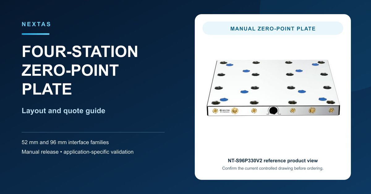
What “four-station” means here
NEXTAS catalogs the P220 and P330 as four-station zero-point plates. That name describes the plate layout. It does not, by itself, tell you whether your project will use one common pallet, several upper fixtures, or separately usable workholding positions. The mating spigots, upper-tool drawings, release arrangement, and application layout answer that question.
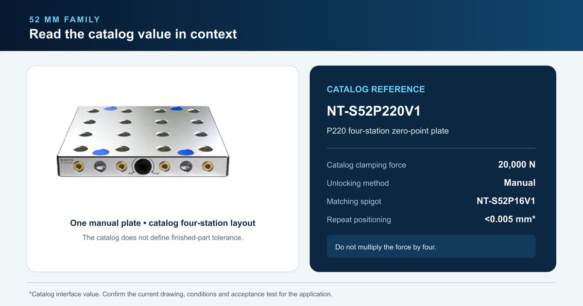
This distinction matters because buyers often compare the wrong numbers. A catalog “clamping force” value belongs to the listed plate model. It is not automatically a per-station force, a workpiece clamping force, or a finished-fixture load rating. Likewise, repeat positioning at the plate interface is not the same as the tolerance on a machined feature.
| Catalog field | 52 mm family | 96 mm family | How to use it |
|---|---|---|---|
| Four-station model | NT-S52P220V1 | NT-S96P330V2 | Confirm the current part number and drawing revision on the quotation. |
| Catalog clamping force | 20,000 N | 30,000 N | Do not multiply by four; ask how the field is defined for the proposed load. |
| Unlocking method | Manual | Manual | Keep the operating port accessible after the fixture stack is installed. |
| Matching spigot | NT-S52P16V1 | NT-S96P20V1 | Match the exact interface, not only the nominal family size. |
| Repeat positioning | <0.005 mm | <0.005 mm | Treat this as a catalog interface value; prove the complete process separately. |
The catalog also lists a 4 × 90° fixed indexing position for these families. That describes available indexing orientations. It does not mean “four stations,” four times the force, or four parts per cycle. Small wording differences like this are why the drawing should lead the comparison.
Will all four stations fit at the worst machine angle?
A top-view CAD screenshot is not enough. On a three-axis VMC, the hidden problem may be the toolholder sweeping past the next fixture. On a trunnion machine, it is often the complete stack at the worst B- or C-axis position. On an HMC, include the tombstone face, spindle approach, pallet change envelope, and anything the operator must reach between cycles.
Build the layout from the machine outward. Use the machine table or rotary drawing, adapter plate, zero-point plate, spigots, upper fixture, jaws, raw stock, finished-part envelope, and longest relevant tool assembly. Add the probe body and stylus as a separate swept volume. A part may fit during cutting and still block probing or loading.
- Neighbor clearance: check each tool and holder against the part and fixture beside it, not only against the machine enclosure.
- Access for cleaning: the locating faces must be visible and reachable. A station that collects chips behind a jaw can become the least repeatable position.
- Manual release access: leave room for the actual operating tool and hand position. Do not assume the front port remains reachable after hoses, guards, vises, or a common pallet are added.
- Rotary limits: include total mass, center of gravity, and overturning moment from the machine builder’s data. The plate catalog does not publish an application payload for your complete stack.
- Loading path: model the door, crane, robot gripper, or operator approach. If station D can be machined but cannot be loaded safely, it is not production capacity.
A useful first-pass rule is blunt: if a station cannot complete loading, locating, probing, machining, cleaning, and unloading, do not count it in the capacity calculation. Sometimes the right answer is three usable positions on a four-station plate. Sometimes a two-station plate produces more accepted parts per shift because it leaves the spindle and operator a clear path.
Follow the load path, not the headline force
Start at the cutting edge and trace the load through the workpiece, jaws or fixture, upper plate, spigots, receiver plate, adapter, and machine table. Every joint can add deflection or moment. The zero-point interface is only one link.
For a common pallet supported across several locations, look at the support span and how cutting torque moves through the pallet. For several upper fixtures, check the worst loaded station and the empty-station condition. A high center of gravity or an interrupted cut can create a moment that a simple vertical force comparison misses. Because the public plate data does not state an allowable application load or moment for P220/P330, the machine limits and an engineering review remain necessary.
Keep four terms separate in the RFQ: catalog plate clamping force, upper-fixture workpiece clamping force, machine or rotary load limit, and the finished-part tolerance. Writing “30 kN required” without naming which one invites a wrong quotation.
Prove stations A–D before releasing production
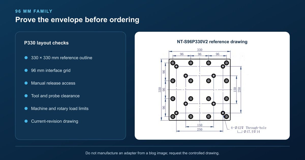
Do not accept one indicator sweep on the easiest station as proof of the whole plate. Label the intended positions A–D on the layout and agree the test method before the trial starts. Use one reference pallet or fixture so the station comparison does not get mixed with four different upper tools.
| Trial | What to do | What the record should show |
|---|---|---|
| Per-station reseat | Remove, clean, reinstall, and measure the same reference on A, B, C, and D for an agreed number of cycles. | X/Y/Z and rotation in the directions that matter, plus temperature, operator, and cleaning state. |
| Cross-station transfer | Move the same reference A → B → C → D without resetting the work offset. | The station-to-station shift, kept separate from repeat seating at one position. |
| Production contamination | Repeat after a representative cutting and coolant exposure, using the planned cleaning routine. | Whether chips are visible, whether the interface seats, and what recovery action is needed. |
| Worst load and angle | Use the heaviest planned fixture condition at the least favorable machine orientation that remains within machine limits. | Clearance, seating, indicator movement, and any access or balance restriction. |
| Fault and recovery | Introduce a detectable dirty or incomplete-seat condition without cutting, then follow the proposed recovery steps. | How the operator identifies the fault, makes the area safe, cleans it, and restores the datum. |
The cycle count is not universal. Agree it from the production risk and the purpose of the test; a seating study is not a life test. More importantly, write the acceptance limit before seeing the data. If a field is unknown, write “unknown” and assign who will close it. That is better than quietly borrowing a tolerance from another machine or plate family.
Run the capacity math with accepted parts
Four fixtures do not automatically mean four times the output. Compare layouts with a simple shop-floor measure:
Net minutes per accepted part = (cutting + loading + cleaning + probing + recovery time) ÷ accepted parts
Here is a hypothetical planning example, not a customer result. Suppose a cycle needs 12 minutes of cutting, two minutes of loading and cleaning, and one minute of probing. If four parts are accepted, the result is 15 ÷ 4 = 3.75 minutes per part. If tool access leaves only two usable stations, the same total time becomes 7.5 minutes per part. Replace every number with measured values from your job; also include any extra indexing or tool travel caused by the wider layout.
Choose one or two stations instead when long tools cross the neighboring envelope, the rotary load or center of gravity is close to its limit, part families have very different cycle times, or cleaning four interfaces becomes the bottleneck. If the real requirement is switching between 52 mm and 96 mm upper tooling on one machine, read the mixed 52 mm and 96 mm interface guide. It treats a combo plate as a drawing-controlled custom layout until fit and load evidence are approved. If the requirement is automated release and clamp-state logic, use the separate pneumatic zero-point plate guide. Those are different decisions.
What NEXTAS needs to review the layout
A useful quotation can start with five groups of information. Missing data is acceptable; label it clearly rather than filling the gap with an assumption.
- Machine: model, table or rotary-face drawing, travel, permitted mass, and center-of-gravity or moment limits.
- Existing interface: pallet, vise, or fixture underside drawing, plus the exact spigot or receiver model if the project must reuse installed hardware.
- Envelope and load: maximum part-plus-fixture dimensions, total weight, and approximate center of gravity for each proposed station.
- Access: worst rotary angle, longest relevant toolholder, probe approach, loading direction, and a STEP assembly of the full stack when available.
- Acceptance: manual operating sequence, datum to be measured, reseat expectation, production contamination condition, and the record required at handover.
Ask for a marked-up four-position layout
Send those inputs with the subject “Four-station plate layout.” NEXTAS can mark up the proposed positions, identify clearance and interface unknowns, and propose an application-specific seating test before a production quotation.
Send the project details →Four-station zero-point plate FAQ
Does a four-station plate always hold four independent workpieces?
No. Four-station is the catalog plate classification; the actual layout may support one common pallet, several upper fixtures, or separately usable positions. The mating interfaces and current drawing must define the station map before quotation.
How should I choose between the 52 mm and 96 mm four-station plates?
Start with the installed spigot or interface family, then compare the full fixture envelope, tool access, rotary limits, and support needs. The catalog force figures alone do not decide which layout fits the machine.
Can I multiply the catalog clamping force by four?
No. The catalog field is tied to the plate model, and the published material does not define a per-station value or a rule for adding the forces. Ask engineering to state the force definition and applicable load conditions.
Does the repeat-positioning value guarantee my finished-part tolerance?
No. Interface repeat positioning does not include fixture deflection, workpiece clamping, machine geometry, tool behavior, temperature, or inspection uncertainty. Prove the complete process with the intended fixture and part.
Is this a drop-in replacement for a LANG Quick-Point plate?
No drop-in compatibility is claimed. NEXTAS is an independent supplier and is not affiliated with LANG Technik or the Quick-Point brand. Compare the exact mating geometry, mounting pattern, stack height, actuation, and acceptance test before any conversion.
Catalog note: Product fields in this guide are taken from the NEXTAS 2026 quick-change clamping catalog. The zero-point clamping plate product page, current quotation, and controlled drawing should be checked together before ordering.