
Planning example: should a 720 × 450 mm pallet use four 120 mm receivers, four 160 mm receivers, or six smaller modules? The pallet outline alone cannot answer that. Neither can total mass. Receiver size and module count work together. Each solves only part of the fixture problem.
The size class points you to a receiver family. The layout controls how the pallet sits across its base. The final choice must hold under real cutting loads and machine motion. It must also fit tool access, air routing, and changeover.
The short answer:
Use the 85, 120, 160, or 195 mm table to open the discussion. Use the complete moving stack and interface drawing to close it. A planning pattern is not an allowable-load rating.
Receiver size and module count are two linked decisions
A common request begins with one number: “My fixture weighs 180 kg. Which receiver do I need?” Weight matters, but it does not show the load path. The same mass can act very differently. One plate may be compact. Another may be wide, with its centre of gravity high above the base.
Start by separating three terms that are often mixed together:
- Receiver class is the nominal 85, 120, 160, or 195 mm family name.
- Module count is the number of receivers under one pallet or fixture.
- Plate pitch is the centre-to-centre pattern on one quick-point plate. A 52 or 96 mm pitch is only one plate pattern. It is not another name for an 85 or 120 mm receiver.
The nominal class does not promise an exact outer size or mount. Use the chosen model drawing for ports, holes, studs, sensing options, and the real envelope.
Current V1 receiver data: what the numbers do and do not say
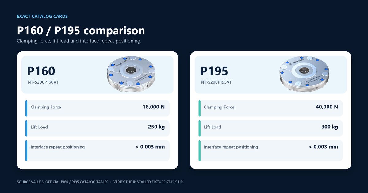
The current NEXTAS V1 family data below gives a clean starting point. Repeatability is listed as strictly below 0.003 mm for all four named V1 models. Clamping force and catalog lift load change by model.
| Named model | Nominal class | Clamping force | Catalog lift load |
|---|---|---|---|
| NT-S200P85V1 | 85 mm | 4 kN | 30 kg |
| NT-S200P120V1 | 120 mm | 12 kN | 100 kg |
| NT-S200P160V1 | 160 mm | 18 kN | 250 kg |
| NT-S200P195V1 | 195 mm | 40 kN | 300 kg |
Read each column for its stated job. Clamping force is a model value. Lift load is the catalog label for that model. It is not the safe moving load of a complete pallet. Do not multiply it by the module count. That does not give a safe fixture limit.
Why not? A full system sees moments and shock. It also sees uneven support, plate bend, cutting loads, machine motion, and real contact. One lift-load number cannot cover those effects.

Use the receiver-count table as a first pass
The counts below are fictional layout assumptions for a first calculation, not published receiver-count recommendations. Determine the actual count and positions from the selected model, support geometry, combined forces and moments, mounting stiffness and agreed reserve.
| Nominal class | First-pass pattern | Useful starting context | What can change it |
|---|---|---|---|
| 85 mm | 3–4 receivers | Compact pallets and lighter fixture stacks. | Small footprint, limited mounting depth, or a load path that needs a different support plan. |
| 120 mm | 4 receivers | General pallet and fixture layouts. | Higher centre of gravity, long overhang, side cutting, rotary motion, or tool-access limits. |
| 160 mm | 4–6 receivers | Larger or heavier fixture stacks. | Wide span, plate deflection, uneven support, robot handling, or routing space. |
| 195 mm | 6–8 receivers | Large pallets and demanding automated layouts. | Machine envelope, added module mass, mounting depth, cost, and the real load distribution. |
These rows are not a ladder that every project must climb. A larger receiver is not always safer. It may add force, yet it also adds weight and takes more room. That can block access or make the pallet harder to handle.
A smaller module is not always cheaper either. More receivers add machining, air lines, check points, and stack-up work. The best design uses the smallest full layout that passes the named load case. It must also fit the machine.
Build one load-case sheet before choosing the count
Ask for the information below before anyone freezes the receiver pattern. If one item is unknown, mark it unknown. Do not replace it with a number from a different fixture.
| Input | Record this | Why it changes the layout |
|---|---|---|
| Moving stack | Pallet, subplate, fixture, workpiece, fasteners, grippers, and any carried accessories. | Leaving out one layer understates the mass and centre of gravity. |
| Centre of gravity | X, Y, and height above the receiver interface for the worst loaded condition. | A high or offset centre of gravity increases the applied moment. |
| Footprint and support | Plate outline, receiver coordinates, bearing pads, gaps, and overhangs. | The span between supports drives local bending and contact reaction. |
| Machining load | Operation, tool, material, cutting direction, and the best available force or torque estimate. | Side milling and interrupted cuts can load the same pallet in different directions. |
| Machine motion | Linear acceleration, rotary indexing, vertical orientation, and emergency-stop case. | The fixture may see its worst case away from the cutting position. |
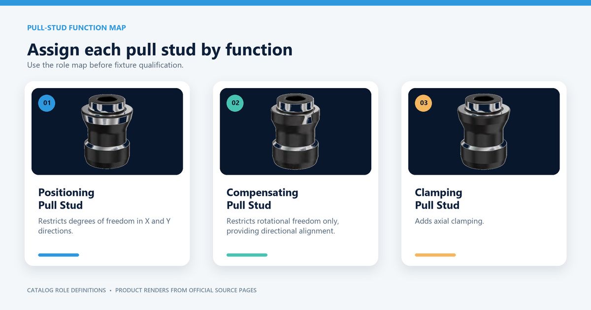
| Datum plan | Which interface locates position, which compensates, and which only clamps. | Too few constraints allow motion; the wrong mix can over-constrain the pallet. |
| Services and access | Air entry, sensors, chip clearance, tool path, robot fingers, and maintenance access. | A mechanically strong pattern can still be impossible to plumb or service. |
For an outside force, the applied moment grows with distance from the base. Force times lever arm is a useful input. It is not a safe receiver limit. The chosen drawing, plate check, fasteners, support loads, and project safety method still rule.
One, two, four, or six-plus: what changes in the datum plan
One receiver plus anti-rotation. One receiver may locate a point. It may still need a clear angle datum. That feature may be a stud, key, pin, or other planned interface. A round interface does not always stop rotation. Check the exact design.
Two receivers in line. A dual layout often uses one position role and one float role. The second point can then support and turn the pallet without fighting the first point. The chosen stud and receiver drawing must define the pair.
Four receivers. One current NEXTAS example uses one positioning point. It also uses two compensating points and one clamping point. It is not a set rule for every four-module product or pallet.
Six or more receivers. A larger array can shorten open spans. It can also spread contact across a large base. Yet it makes plate flatness, machining limits, air routing, and checks harder. More modules cannot fix a weak plate on their own.
Watch a four-receiver layout before freezing the plate
The short official NEXTAS video shows four receiver positions on a demo board. It also shows the air-route area. Use it to discuss access and layout. It does not name an exact receiver model. It also does not prove spacing, load, repeatability, or cutting results.
Official NEXTAS layout view
Four-Receiver Zero-Point Clamping Layout
An 18-second demonstration-board view from the official @Nextas-Sandy channel. Use the visible positions and air-routing context only as a discussion aid.
Send your layout for reviewWhat must be checked on the selected-model drawing
Once the first-pass class and pattern look sound, move to the exact model. Check its outer size, hole pattern, depth, stud form, and support faces. Then check the air port, release pressure, and any sensing or air-blast option. Confirm tool, chip, robot, and service access around the full stack.
An earlier article retained a 6 bar release example without independent catalog verification. The current family page does not establish a uniform release pressure. Confirm pressure and air quality at the receiver from the selected released model drawing and circuit. Air blast, lift aid, pressure checks and seating feedback require the actual selected functions and arrangement.
Safety boundary:
Spring locks with air release do not make a machine or cell safety-rated. Normal clamp, seat, and pressure signals are process signals. They are not safety signals unless the full safety function is designed and tested. Define what happens with low pressure, lost air, or an emergency stop. Also define restart, sensor conflict, and an incomplete release.
Accept the mounted stack, not a catalog row
Test the real stack. Include the pallet, fixture, part, supports, studs, receivers, valves, tubes, and control steps. Clean-cycle results help. Yet shop chips and coolant can change seating and release.
- Inspect before cycling. Check support contact, receiver seating, stud fit, bolt torque, line routing, and tool space.
- Cycle the worst position. Use the heaviest approved stack and highest centre of gravity. Include the longest overhang and the hardest machine move.
- Measure the result. Record the seated state and full release. Log circuit pressure, repeatability at the work datum, and any alarm or retry.
- Test the approved shop condition. Use the specified chip and coolant condition under the written acceptance method. Do not deliberately add debris unless the supplier, machine owner, and safety owner approve that method. Check that the planned cleaning features and service access work.
- Freeze the proof. Save the final drawing revisions, receiver and stud models, test steps, results, limits, and sign-off.
Reopen the review when the load case changes. A heavier part or taller fixture may break an old pass. So can a new side cut, faster index move, or moved receiver. The model names may stay the same while the risk changes.
Send a package that can be engineered
A useful request for quotation (RFQ) does not ask only for “four 160 mm modules.” Send the machine table drawing and the computer-aided design (CAD) files for the pallet and fixture. Give the total moving mass, centre of gravity, part size, operation, and cut direction. Add the machine motion and any proposed receiver points. Include the air and signal plan plus the required changeover steps.
Mark each value as measured, estimated, or still open. Add units and drawing revisions. This stops the quote from hiding an assumption.
Send this package for an engineering review. NEXTAS can then compare each class and layout against the same facts.
Common questions about receiver size and module count
Can receiver diameter alone determine the module count?
No. Diameter identifies a receiver class. Count and spacing also depend on the full moving stack, centre of gravity, footprint, cutting direction, support span, machine motion, and datum plan.
Is the 195 mm receiver always the safer choice?
No. A larger receiver can add capacity, but it also changes weight, envelope, plate design, access, and cost. The smallest verified system that fits the complete load case is often the better design.
Can a zero-point system use only one or two receivers?
It can, but the exact interface must define angular location, support, and the applied load case. A single receiver may need a separate anti-rotation feature. A dual layout commonly assigns positioning and compensation roles according to the selected drawing.
Does catalog lift load equal safe pallet payload?
No. Lift load is a catalog value for the named model. It is not a complete dynamic pallet rating and should not be multiplied by receiver count to approve a fixture.
What should I send NEXTAS for a receiver recommendation?
Send the machine table drawing, pallet and fixture CAD, total moving mass, centre of gravity, workpiece envelope, cutting-force direction, machine motion, air and signal plan, and the required changeover sequence.