
The short answer: approve the complete rotating stack, not a product family
A zero-point clamp may make a tool change quick. It may also add height, mass, hoses, plugs, and a new release step to the rotary axis. These changes affect tool reach, balance, space, and safety. A close-looking photo, shared pitch, or brand name cannot prove fit.
Start with the exact table drawing. Add the adapter, clamp units, studs, pallet or vise, part, and each fitting. Show the whole stack at each work angle. Mark its mass and centre of gravity, which is its balance point. Show how air lines and wires move. Block release unless the table and load are in the approved change state.
A release-ready proposal has four controlled items:
- One fit drawing for the exact table and chosen zero-point parts.
- A space check for the full stack, tools, guards, hoses, and fittings.
- A mass and balance-point check against the table maker's limits.
- A lockout and test plan that blocks an unsafe release.
Freeze the rotary-table baseline before choosing hardware
Record the table maker, model, serial or build option, and machine setup. Get the current table-face drawing from its owner. It should show the face size, centre feature, bolt or T-slot grid, locating points, thread depth, and no-drill zones. Add the axis centreline and the machine's home direction.
Ask the table maker for the limits for this setup. These may cover table load, overhang, inertia, balance-point distance, speed, and brake or hold limits. Use the maker's own terms and values. Do not copy a limit from another table size or a close-looking unit.
Record what is on the machine now. Include any subplate, tailstock, rest, cable track, rotary union, guard, probe, tool changer, and door path. If the drawing and the real machine do not match, stop and fix the baseline. Design for the machine that exists.
Make one interface drawing that closes both sides of the fit
The drawing must link the table face to the adapter and clamp base. It must also link the chosen receiver to its stud and top fixture. Mark each pilot, bolt circle, thread, seat, and key. Name the owner of each item. Show room for install and service tools.
A 52 mm, 96 mm, or receiver-family label is not enough. The NEXTAS zero-point receiver page lists single modules and multi-station blocks. The separate manual plate page and pneumatic plate page describe different hardware. Do not mix their force, release, or stud data.
The examples below stay with exact MFG receiver models. They are not table picks. They show why the part number and signed drawing must stay together.
| Exact receiver | Published data | Still needed for a rotary table |
|---|---|---|
| NT-S200P85V1 | 85 mm module; 4 kN clamping force; 30 kg lifting load; ≤0.003 mm repeatability. | Mounting drawing, receiver mass, support plan, circuit, and table-limit review. |
| NT-S200P120V1 | 120 mm module; 12 kN clamping force; 100 kg lifting load; ≤0.003 mm repeatability. | Exact stud, orientation, adapter, stack, and rotating envelope. |
| NT-S200P160V1 | 160 mm module; 18 kN clamping force; 250 kg lifting load; ≤0.003 mm repeatability. | Load path, centre of gravity, routing, release interlocks, and acceptance limits. |
A lifting-load value is not the table's mass limit. It does not approve the unit for cutting. The repeatability value belongs to the named receiver and its test. It does not cover adapter error, table error, fixture bend, or cross-station shift. Ask for the drawing, mass, circuit, and test scope for the chosen setup.

Calculate the full stack height from the axis centreline
Stack height is more than the receiver depth. Add the table face, adapter, receiver, stud, pallet, fixture, jaws, part, and each spacer. Measure from one fixed table or axis point to the top and outer edge. Include bolts, fittings, sensor plugs, and lift points that stay on while the table turns.
A tall stack can cut tool reach and move the cut farther from the axis support. It can also put the part near a guard, spindle head, toolholder, probe, or door. Check the short tool that must reach and the long tool that may pass by. Check the tool-change path too.
Put the full stack in the machine model. Turn it through each work angle. The swept envelope is the space it uses as it turns. Check work and load positions. Show real hoses, plugs, clamps, and cable bends. Do not hide them to make the model fit.
Add every moving mass and locate the centre of gravity
List the mass of the adapter, clamp units, studs, pallet, fixture, part, jaws, clamps, moving hoses, and any balance weight. If a needed mass is not on the product page, ask for it with the chosen drawing. Do not enter zero or use the mass of another model.
The centre of gravity is the balance point of all that mass. Its gap and direction from the rotary axis matter. The same mass can make more work for the axis when it sits far from the centre. A tall fixture or off-centre part can add a large turning force even when the table-load figure looks safe.
Send the mass list and balance-point spot to the table maker. Add the planned speed and move profile. The zero-point supplier can check its clamp fit and load path. It cannot replace the table maker's limit check. Keep both sign-offs with the final drawing.
Draw cable and hose routing in the swept envelope
A hose that is safe at zero degrees may pull tight, rub, kink, or reach the tool path after a turn. A plug may be the widest point in the stack. Show each air line, sensor wire, fitting, joint, bracket, and strain-relief point.
Mark what stays fixed and what turns. If the table has a rotary union or inner path, ask the table maker which fluid, port, pressure, flow, and signal it can take. Do not use a spare-looking port by guess. For an outer loop, check bend, twist, rub, chips, coolant, and full travel both ways.
The route must also be easy to check for wear. A broken line or lost signal needs a clear fault response. A safe hose path does not prove a safe release state. Keep the route, I/O proof, and safety checks as separate items.
Make unintended release a denied state
Block the release output during cutting and normal table motion. Allow it only at the agreed change point. The axis, spindle, load tool, guard state, and load support must all be in the set state. The real checks depend on the machine and load method.
If a robot lifts a pallet, prove that its gripper holds the load before release. If a person changes the clamp, the safe access and lockout plan must protect that person. A normal CNC M-code or PLC bit is not a safety function by default. The machine builder and cell firm must choose the right safe parts and logic.
Check fault states too. Ask what happens after lost air or power, a stuck valve, lost proof, a table stop between points, or a pallet that will not seat. Confirm the chosen receiver's real lock and release circuit. Do not assume all product lines act the same. A reset must not cause motion or release until the fault is known and the safe state is back.
Use the 13-second video for layout context only
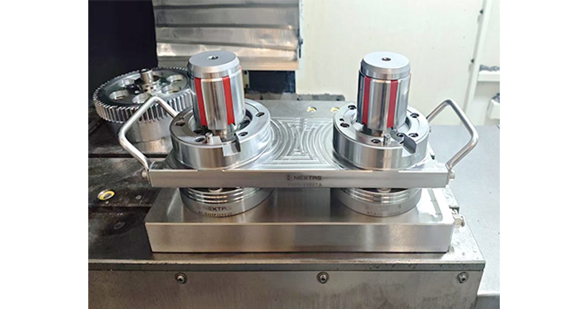
A 13-second view of a double-sided dual-station zero-point arrangement on a rotary setup; it does not prove fit, load, balance, repeatability, routing, release safety, or compatibility with another table.
Release the design in three evidence gates
Gate one is the drawing check. Confirm the exact table, adapter, receiver, stud, pallet, fixture, bolts, ports, sensors, stack size, mass, balance point, and route. List open items. Do not order or cut the adapter while a locating point, table limit, or release circuit is still a guess.
Gate two is the fit check. Inspect the seats and mount parts. Build the stack by the signed plan. Measure its height and clear space. At the set test speed and under the machine builder's controls, turn through the full path without cutting. Watch hoses and wires. No one should stand in the swept space to guide a line by hand.
Gate three is the use test. At the agreed change point, test seating, lock, release, and each lost signal. Prove that release stays blocked in each banned state. Repeat clamp changes and measure one known datum. Run real work next and check the parts against limits set before the trial.
- Pass: drawings match the real setup, travel and lines stay clear, table limits have sign-off, and all release and gauge tests meet the written limits.
- Revise: if an adapter, stack, support, route, signal, or reset step changes, fix the drawing and test that gate again.
- Stop: table ID, fit, mass, balance point, safe release state, or pass limit is unknown.

Send a drawing-led RFQ
Send the machine and table make, model, serial or option, face drawing, axis height, work space, and the maker's load and balance-point limits. Add the adapter idea, clamp layout, pallet or fixture drawing, part range, full mass list, and balance-point spot.
Add the work angles and speed, tool and probe space, load method, air or oil service, wire and hose route, sensor needs, change point, blocked release states, and pass limits. Ask NEXTAS to name the receiver, stud, drawing, circuit, mass, and records for the quote. Ask the table maker and cell firm to sign off the parts they own.
Need an interface review?
Share the table drawing, rotating stack, and release conditions
NEXTAS can review the supplied workholding inputs and identify candidate receiver data, interface gaps, and questions for the table maker or integrator.
Questions buyers ask about rotary-table integration
Can a zero-point system fit any 4-axis rotary table?
No. Fit depends on the exact table face, locating features, bolt pattern, thread depth, adapter, receiver, stud, stack, load, and routing. Confirm all of them on a reviewed drawing. A brand name, photo, or shared pitch is not compatibility proof.
What must the interface drawing show?
Show the table face and axis datum, adapter, selected receiver and stud, locating and seating faces, bolts and thread engagement, orientation, ports, sensors, service access, full stack dimensions, mass, centre of gravity, and cable or hose path.
How should I calculate stack height?
Add every layer from the rotary face to the highest and widest point: adapter, receiver, stud, pallet, fixture, jaws, workpiece, fasteners, fittings, and connectors. Then check the swept envelope at every planned angle and during tool change.
Why do total mass and centre of gravity both matter?
The same mass can place a different demand on the rotary axis when it sits farther from the centreline or to one side. Add every moving item, locate the combined centre of gravity, and have the table maker review it against the limits for that exact installation.
How should air hoses and sensor cables be routed?
Draw every line through the full rotary travel. Confirm fixed and moving points, bend and twist, strain relief, fittings, chip and coolant exposure, and service access. Any rotary union or internal port must be approved for the stated medium and duty.
What prevents an unintended unclamp?
Release must remain denied outside the approved exchange state. The design should check axis and spindle state, load support or robot grip, guarding, and required feedback. The machine builder and integrator must validate the real interlocks and any safety-rated functions.