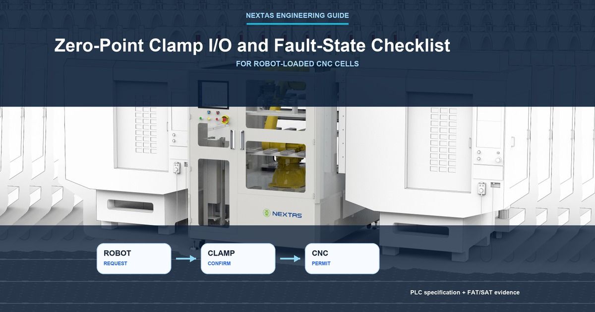
The programmable logic controller (PLC), which runs the normal sequence, has turned on the clamp command. Is the CNC ready to start cutting? Not yet. A command proves only that the controller asked the clamp to move. It does not prove that the pallet is seated, the clamp reached the locked position, or the robot moved away.
This guide is for anyone buying, building, or accepting a robot-loaded CNC cell. Input/output (I/O) means the signals shared by the clamp, robot, PLC, and CNC. A normal interlock is a condition that blocks a process action until its required evidence is present; it is not automatically a safety function. A fault state means those signals are missing, disagree, or do not prove one clear physical condition.
In plain English, agree on four things before commissioning:
- which signal proves each real condition;
- which next action must wait for that proof;
- what the cell must do when signals disagree; and
- who checks the problem and allows the cell to restart.
Normal control signals are not the machine’s safety system
Most signals in this checklist are normal control signals. They tell the clamp to open or close, report a sensor, show that a pallet is present, tell the robot when it may load, or tell the CNC when the normal work sequence may continue.
Important safety boundary: these signals help equipment work in the right order. They do not replace guards, emergency stops, safe robot-position functions, spindle safety functions, prevention of unexpected start-up, or the cell risk assessment.
ISO 10218-2:2025 covers the integration and commissioning of industrial robot cells. ISO 13849-1:2023 gives a method for safety-related control systems. The machine builder and safety specialist must still choose and validate the safety functions required for the actual cell.
Universal Robots, for example, documents normal digital I/O separately from safety I/O. This is one controller example, not a wiring rule for every robot.
Describe what the cell can prove right now
A PLC state should describe what the sensors actually prove, not what the last command asked the hardware to do. After power returns, the state should remain unknown until the PLC reads the real clamp and pallet signals again.
- Open confirmed: the chosen open sensor is ON, the locked sensor is not ON, and the pallet-handling conditions are known.
- Robot loading: the normal work sequence asks the robot to load, while the separate safety system also allows the planned robot action.
- Pallet placed: the required pallet-present or pallet-ID signal is correct. The robot and gripper may still be near the fixture.
- Clamp moving: the released support/retention conditions and clearance from the moving clamp envelope are confirmed, so the PLC may ask the clamp to lock. This does not necessarily mean the robot has withdrawn or released its grip.
- Locked and checked: the open and locked sensors agree, and any required pallet-seat or cleanliness check has passed.
- Fault or unknown: signals conflict, are missing, are too old to trust, or were lost after a power, air, or communication interruption.
If any required proof is missing, the next automatic action stays blocked. If the design has no separate seat sensor, write that down. If “robot clear” is only a normal program signal, do not call it proof of a safety-rated robot position.
Give every signal one owner and one clear meaning
A useful I/O contract is simply a signal list that leaves no guessing. For each signal, write who sends it, what ON and OFF mean, what physical condition it really checks, who uses it, what must stop if it is missing, and who may reset the fault.
Also record the power-up state, drawing or manual reference, agreed maximum wait time, and how the PLC handles short signal flickers. If a value is missing, write unknown and ask for the real document. Never copy a timeout, voltage, polarity, or retry count from another machine.
| Signal | Where it comes from | What it really tells you | What it does not prove |
|---|---|---|---|
| Clamp or unclamp command | Cell PLC or chosen sequence controller | The controller asked the valve or actuator to move. | That the movement finished. |
| Clamp or unclamp feedback | Named sensor and PLC input | The exact condition that sensor can see. | More than the sensor’s stated function. |
| Pallet present or pallet ID | Named sensor, reader, robot, or fixture device | A pallet is detected and, when required, it is the expected pallet. | That the pallet is fully seated. |
| Seat or cleanliness check | Chosen sensing arrangement | The measured seat or air condition within its stated limits. | Any condition the sensing method does not measure. |
| Air-pressure signal | Pressure device at a named point in the air circuit | Pressure is available at that measuring point. | That the pallet is seated or the clamp is locked. |
| Robot or gripper clear | Robot or cell controller | The exact normal program state represented by the signal. | A safe robot position unless the safety design separately proves it. |
| CNC ready or cycle status | CNC interface | The agreed machine mode, program, door, or cycle condition. | That every clamp, pallet, robot, and safety check is complete. |
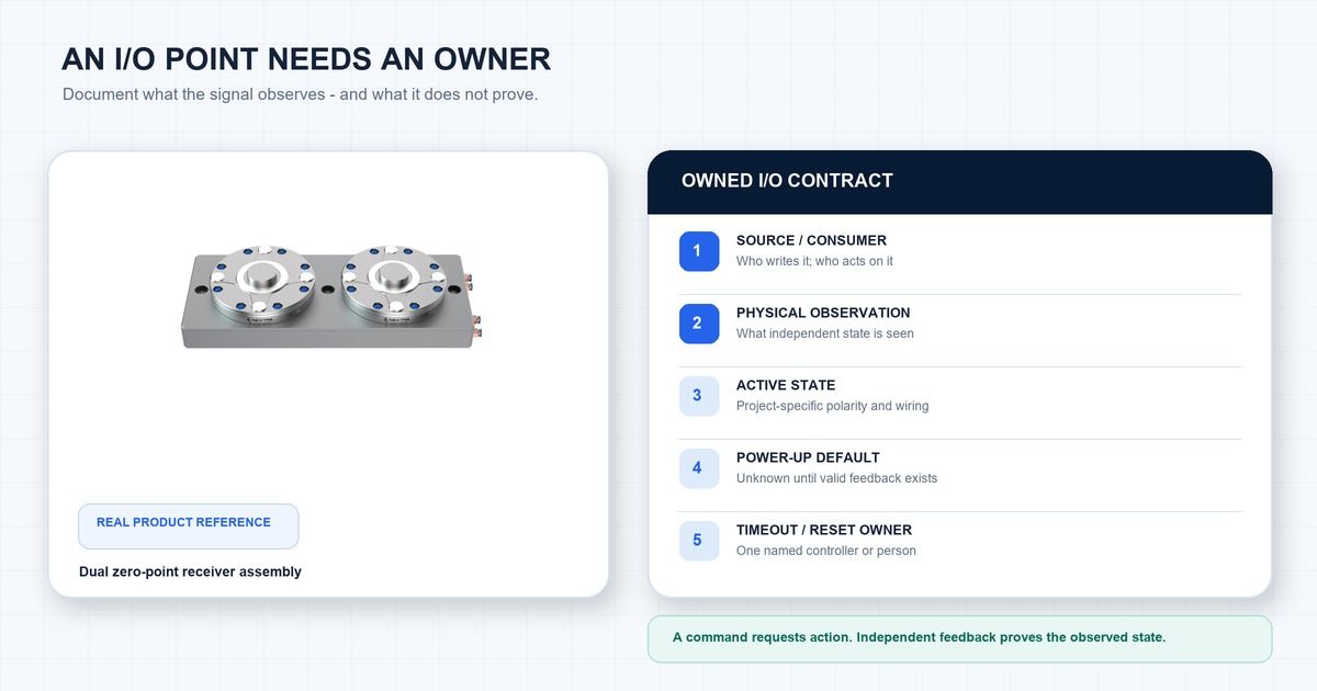
Ask one practical question about every feedback signal: Could this input look normal while the hardware is wrong? If the answer is yes, add that case to the fault test.
Write the robot–clamp–CNC sequence step by step
Controls engineers call the ordered requests and confirmations a handshake. The example below must be adapted to the released assembly and integration plan. Establish stable support and retention before any handoff or unclamping; vertical or overhung loads may require lock confirmation before the gripper releases. Define clamp-envelope clearance separately from complete robot withdrawal:
- The CNC reports that it is ready for pallet exchange. The cell also checks that no normal process fault blocks the exchange.
- The clamp opens and the open sensor confirms it. The unclamp command alone cannot move the sequence forward.
- The PLC asks the robot to load. The normal work sequence and the separate safety system must both allow the planned robot action.
- The robot places the pallet. The cell checks the required pallet-present, pallet-ID, or seat signal. “Robot move complete” is not enough.
- Confirm the released support and handoff conditions. The pallet must remain stably supported or retained. Depending on orientation and overhang, confirmed fixture retention may be required before gripper release. Clearance from moving clamp elements is not the same as robot withdrawal.
- Lock, confirm retention and release the gripper in the approved order. The selected assembly and integrator define that order and the robot withdrawal step. The project team sets the maximum wait time from the actual clamp, valve, air circuit, controller, network, and test results. If confirmation is late, the sequence stops and raises a fault.
- The CNC receives permission to cut. This normal permission requires the agreed clamp, pallet, seat, robot, gripper, CNC-ready, and fault checks. The machine-safety system remains separate.
Review this plain-language sequence together before anyone writes PLC code.
Choose the stop action before a fault happens
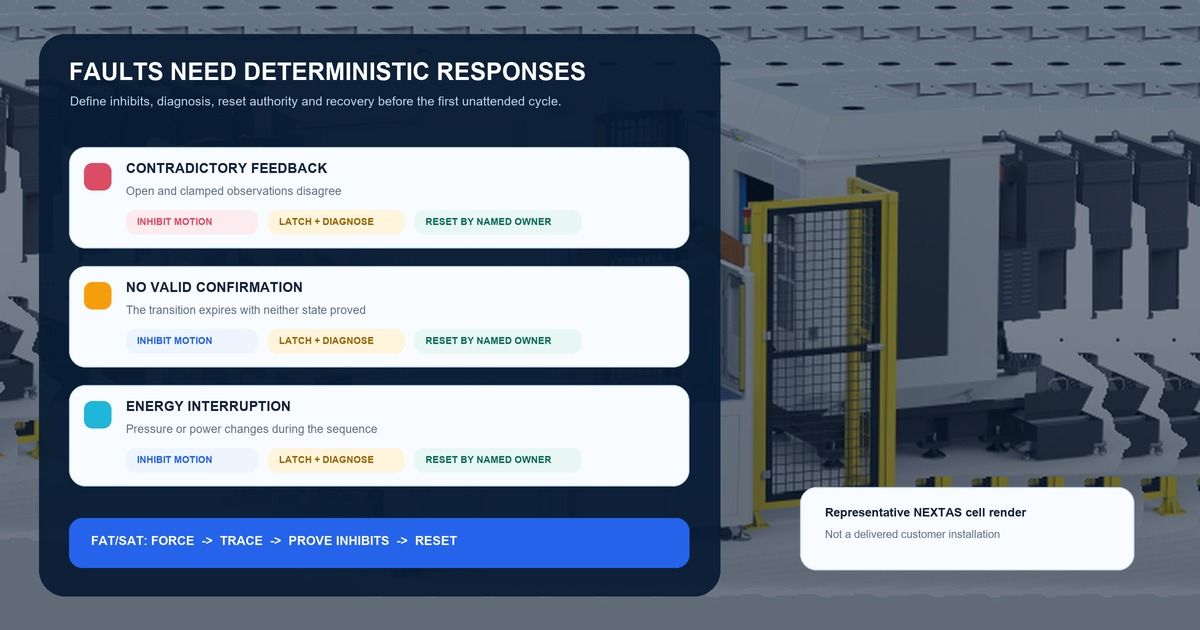
A fault matrix says what must stop, what must be checked, and who may reset the problem. Agree on it before the factory test.
| Problem seen | What the cell must stop | What must be checked before restart | Who may reset |
|---|---|---|---|
| Open and locked feedback are ON together | Hold the automatic sequence and block the related robot and CNC run commands. | Check the sensors, targets, wiring, PLC logic, and drawings until one clear state is shown. | The named controls or maintenance owner. |
| Neither state is confirmed after a command | Stop the step when the agreed wait time ends. Do not keep retrying. | Find the mechanical, air, sensor, or wiring reason before an approved retry. | The sequence controller or operator named by the project. |
| Air-pressure signal is missing | Block any action that depends on that pressure. | Check the actual module, valve, air line, and pressure-device documents. Pressure alone does not prove locking. | The air-system or maintenance owner. |
| Pallet is missing, wrong, or not proved | Block CNC Cycle Start. | Use an approved unload or recheck sequence after the robot, gripper, and machine conditions are known. | The cell controller and operator where inspection is needed. |
| Seat or cleanliness check fails | Do not mark the clamp state as ready for machining. | Use a documented clean-and-reseat step with a clear limit and end condition. | The sequence owner, then the operator after allowed attempts end. |
| Robot or gripper clear is missing | Block CNC Cycle Start and every motion lacking its required clearance. A retention action is allowed only where the released sequence explicitly permits it with stable support and the correct clamp-envelope clearance. | The robot owner must correct the signal or physical condition. The PLC must not hide it. | The robot or cell-controls owner. |
| Power, communication, or air is interrupted | Do not continue the automatic cycle from memory. | Read the real sensors again and confirm the planned power-up output states. | The named cell-recovery owner. |
A reset is not the same as recovery
Three separate things must happen after a fault:
- The cause is removed. For example, the air supply returns or a loose sensor cable is repaired.
- The alarm is acknowledged. The named person or controller accepts the reset.
- The cell proves that it may restart. The PLC reads the real sensors again, returns to a known state, and starts a fresh normal sequence.
An automatic retry is reasonable only when the starting state, allowed action, maximum number of attempts, stop condition, alarm record, and handoff to a person are all written down. If the PLC still cannot tell whether the clamp is open or locked, the cell has not recovered.
Test the planned faults before production
FAT means factory acceptance testing before shipment. SAT means site acceptance testing after the cell is installed. Both should include planned fault tests, not only a successful automatic cycle.
During FAT, engineers may simulate PLC inputs—often called forced bits—to check program steps, alarm messages, stored faults, reset ownership, and event logs. This checks the software. It does not prove the field wiring, sensor target, valve, air line, or physical pallet seating.
During SAT, repeat the applicable tests through the real hardware using an approved method. Test conflicting clamp signals, one missing signal, loss of pressure indication, a rejected pallet or seat check, robot or gripper not clear, a clamp change that never finishes, and a power or communication interruption. Use a dry cycle without cutting. Tests of safety functions remain in the separate safety-validation plan.
Keep a short record for each case:
- the test case and drawing or software version;
- the starting state and how the fault was created;
- the command and feedback signals in time order;
- which motions or Cycle Start commands remained blocked;
- the alarm, reset owner, and recovery result; and
- the witness, pass or fail result, and required follow-up.
What to send for a useful interface review
For an initial interface review, send at least the selected zero-point module or plate drawing and revision, valve and air-circuit diagram, sensor part numbers and manuals, and PLC/robot/CNC signal list with the planned released sequence. Identify unknown items explicitly. Include the pallet support/retention handoff, required lock/seat evidence, timing limits and fault/reset responsibilities before controller programming.
If available, also send:
- the agreed wait times for clamp movement and other key steps;
- what the outputs do when power returns;
- the planned reset and restart sequence; and
- the person or controller responsible for each fault.
Mark missing information as unknown instead of guessing. NEXTAS can review the mechanical, pneumatic, and available sensor interfaces and flag missing project data for the integrator. NEXTAS cannot approve the complete cell’s safety design, choose its safety functions, or promise controller compatibility before the actual documents are reviewed.
Before controls commissioning
Review your clamp I/O brief
Send the brief above through the contact form and state which clamp signal or fault response you need to confirm.
Discuss your clamp interfacesCommon questions from CNC buyers
If the PLC says “clamped,” can the CNC start cutting?
Not yet. That signal proves only what its sensor measures. The cell should also confirm the correct pallet is present and seated, the robot and gripper are clear, the CNC is ready, and no blocking fault is active. The separate machine-safety system must also allow operation.
Are normal clamp signals part of the machine-safety system?
Not by default. Normal I/O can control the work sequence, but it does not become safety-rated just because the PLC uses it as an interlock. The machine builder and safety specialist must choose and validate the safety functions.
How long should the PLC wait for the clamp to change state?
There is no single time that suits every cell. Set the limit from the selected clamp, valve, air circuit, controller, network, and measured test results. If confirmation does not arrive in time, stop the sequence and show a clear fault.
Who should be allowed to reset a clamp fault?
Name the owner before commissioning. A simple software fault may be reset by the sequence controller or operator. A wiring, sensor, air, or mechanical problem may need maintenance inspection. A safety reset follows the separate safety design.
Can a software simulation replace tests on the real machine?
No. Simulated inputs can check program steps, alarms, and reset logic during the factory acceptance test (FAT). They cannot prove the field wiring, sensors, valves, air circuit, or pallet seating. Check those items on the installed cell during the site acceptance test (SAT).