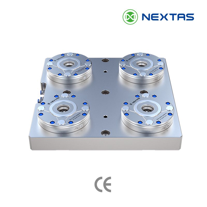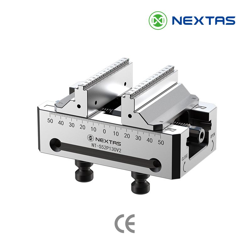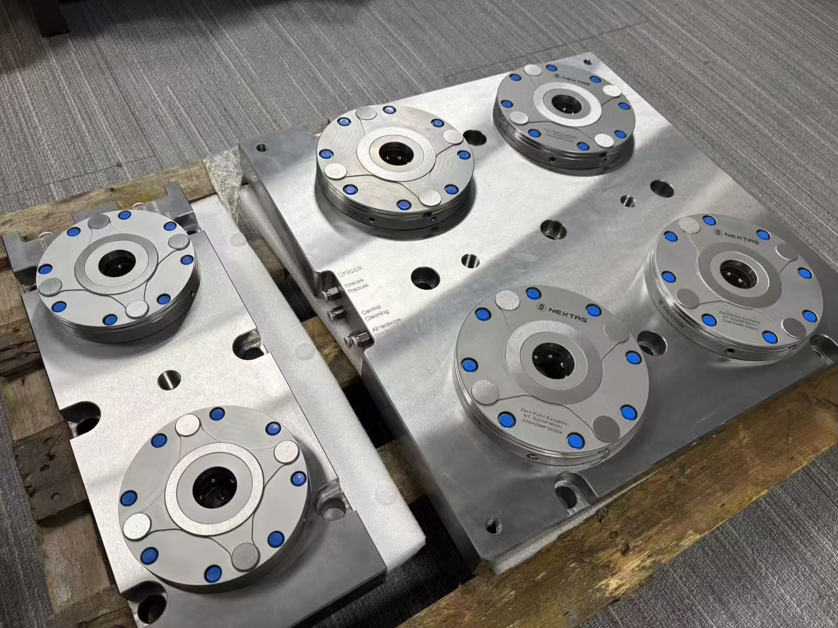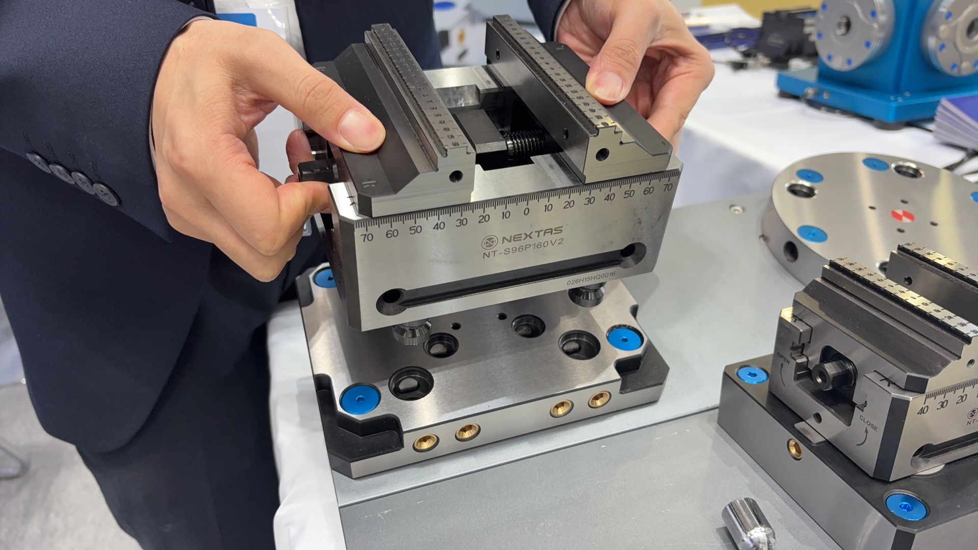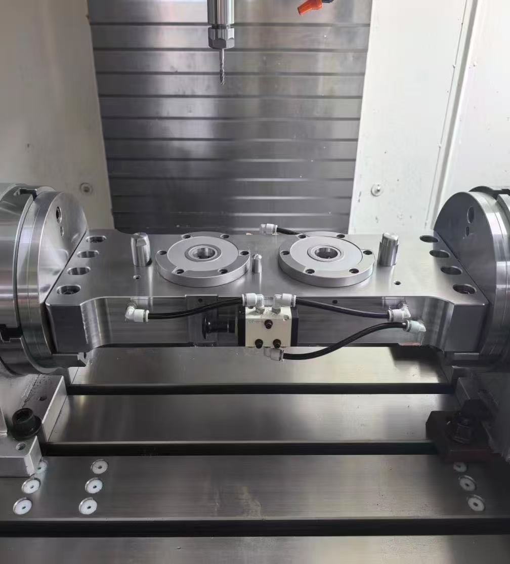
Custom NEXTAS dual-station zero-point bridge mounted on a 4-axis rotary table, featuring integrated guide pillars and a front-mounted manual pneumatic release valve.
The setup: a drop-center dual-station bridge
Every high-mix job shop running a 4th-axis rotary table on a vertical machining center (VMC) eventually hits the same wall: you buy the rotary to cut setups by machining multiple faces in one clamping, yet you lose hours dialing in vises and dedicated fixtures every time the job changes.
When mounting a standard flat bridge plate between a rotary indexer and tailstock, operators are usually forced to bolt fixtures down, sweep the X-axis, and re-probe work offsets. Worse yet, stacking a subplate, a zero-point receiver, and a 5-axis vise directly on top of the rotary centerline eats up valuable Z-axis daylight and increases torque load on the 4th-axis drive.
To break this bottleneck, the engineering team at NEXTAS configured a custom 4-axis zero-point bridge fixture tailored specifically to the VMC's table envelope. Rather than using a flat beam, the bridge features a drop-center geometry bolted directly to the rotary faceplates at both ends (4 bolts per side). Dropping the mounting surface closer to the center of rotation accomplishes two things immediately: it keeps the center of gravity near the rotational axis, and it preserves maximum Z-axis tool clearance under the spindle.
Machined into the hardened bridge are two NEXTAS pneumatic zero-point receiver modules. Because parts and vises are loaded frequently inside a tight machine enclosure, the bridge integrates heavy-duty cylindrical guide pins flanking the receivers, plus a central alignment pin that seats the fixture in only one orientation. Operators don't have to delicately balance a heavy vise over the pull studs; the guide pins catch the fixture first and slide it straight into the tapered receivers without bruising the sealing surfaces.
On-bridge pneumatic actuation
One of the smartest details on this build is right on the front face of the bridge: a direct-mounted manual pneumatic valve manifold plumbed to the receivers via external push-to-connect air lines.
Many shops hesitate to put zero-point systems on a 4th axis because they don't want the expense and maintenance of a multi-port rotary union routed through the indexer. Because NEXTAS zero-point modules use a mechanical self-locking structure with spring-driven clamping and tapered positioning, air pressure is only required for a few seconds to release the pull studs and trigger the auto-lift and air-blast cleaning functions.
During changeover, the operator connects a shop-air line, pulls the manual valve plunger on the front of the bridge to release and eject the current fixtures, drops the next set of pre-staged vises onto the receivers, and pushes the valve back to lock. Once disconnected, the bridge indexes freely across 360 degrees with zero trailing hoses and <0.003 mm repeat positioning accuracy.
Shop-floor impact
- Sub-2-minute changeovers: Swapping between two self-centering vises and a custom part fixture now takes less than 90 seconds, with no indicator sweeping required.
- True one-datum strategy: Workpieces or vises are pre-assembled on pull-stud pallets offline while the spindle is cutting.
- Protected investment: Integrated air-tightness and pull-stud hole cleaning prevent fine aluminum and steel chips from migrating into the locking mechanism during horizontal or inverted indexing cuts.
What to send for a 4-axis bridge layout
Send the rotary model, the table envelope, and whether you need dual stations or a long fixture spanning both receivers. Engineering can start a 4-axis bridge layout from those three facts.
Zero-point systems · Self-centering vise
With the layout request
Send the rotary model
Attach the rotary model, the table envelope, and whether you need dual stations or one long fixture across both receivers.
Contact engineering