
A part model is not a fixture spec. Many quotes start with a STEP file, a machine name, and a cycle-time wish. The builder then has to guess how clamps should move, how hard they should push, and how oil gets onto a spinning table.
Those guesses show up later as a cocked part, a rotary joint that fights the drive motor, or a table teardown to add one more oil line. The cheaper move is to write clamp order, working pressure, ports, and routing before anyone prices the job.
A Request for Quotation (RFQ) is the packet you send so a supplier can price a real design. A rotary union is the rotating joint that carries oil and air from the still machine into a fixture that turns. Name that joint in the RFQ if the fixture will index or mill while it spins.
Use this split:
Locators take the cut. Clamps only hold the part against those locators. If a mill pushes on a live cylinder instead of a hard stop, the part can chatter. Write that load path before you send the quote pack.
What else belongs in the RFQ?
Keep one list. Do not paste it again in the intro, the FAQ, and the last call to action. The full send-list sits at the end of this page.
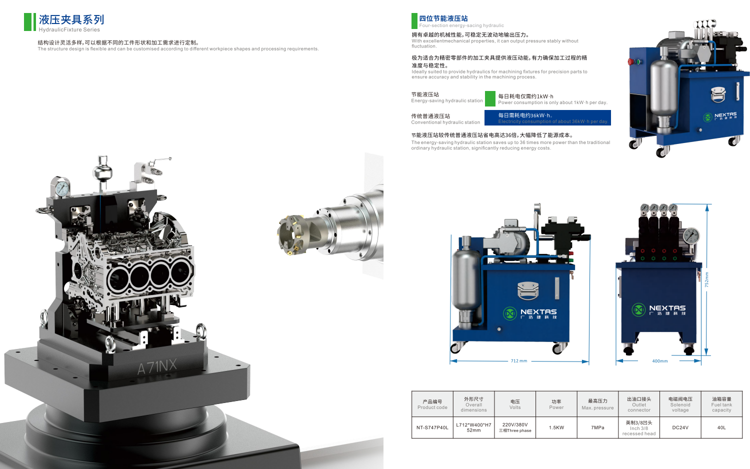
The custom hydraulic fixture page is the source for the published ranges here. Typical listed seating is 0.005 mm or closer. Listed clamp force is 5 to 200 kN and depends on the job. Listed working pressure is 10 to 70 MPa. Some circuits are also reviewed at 70 to 210 bar. The listed NT-S747P40L power unit is a 7 MPa pairing reference. It is not a stand-in for that wider range.
If you are still choosing air versus oil, use the pneumatic vs hydraulic cost guide. If the open question is whether a custom hydraulic fixture even fits the part family, use the automotive hydraulic fixture guide. This page starts after that fork. You already want a custom hydraulic fixture. You need the RFQ to be quoteable.
Clamp order before oil pressure
The first rule is mechanical, not hydraulic. Hard locators set the 3-2-1 frame: three points on the main face, two on a second face, one on a third. Clamps then hold the part on those locators. Do not aim a clamp into the main cutting thrust and hope friction saves you.
A common run looks like this:
- Load the part onto the locators. Use a pin or a shape that only fits one way so the part cannot go on backwards.
- Check that the part is down. A small air hole in a rest pad can show a gap before any clamp moves.
- Bring work supports in gently so they touch the rough shape without lifting the part off the locators.
- Clamp against the rest pads, not past them.
- Lock the work supports so they become rigid columns before the tool cuts.
A work support is a plunger that fills a gap under the part. It is not a clamp. It stops the part from bending down under the cut.
Sequence valves or machine signals?
You still have to say who fires each step.
The split below is a first-pass choice, not a NEXTAS catalog grade.
| Route | How it fires | Watch-out |
|---|---|---|
| Sequence valves on one oil line | Oil reaches the next group after pressure lifts a spring | Saves ports. Cold thick oil can fire the next step too soon. |
| Separate lines and machine signals | Each group has its own valve. The control waits for a proven state. | More repeatable. Needs more ports through a rotary union. |
If the order must be proven, do not leave it to a spring inside a valve. Write the signals in the RFQ.
How hard should the oil push?
Pressure is a trade, not a slogan. Higher pressure lets you use smaller cylinders in a tight machine. Lower pressure spreads the load over a larger piston, which can help a thin aluminium wall.
The NEXTAS listed range is 10 to 70 MPa. Some circuits are reviewed at 70 to 210 bar. The listed four-station power unit is 7 MPa. Size the pump from the circuit, not from that one unit.
This next split is planning talk, not a catalog grade. Shops often treat about 70 to 150 bar as a lower band for soft parts, and 200 bar and up as a compact high-force band for iron and steel. Those bands are common shop ranges. They are not NEXTAS model names. Final pressure still follows the part, the cylinders, and the pressure you can hold at the fixture.
Long swing-clamp arms
A catalog clamp arm is short. A custom arm is often longer so it clears a boss. The extra length raises the bend on the rod.
A first-pass check is this planning math: effective force equals rated force times (standard arm length divided by custom arm length). If the custom arm is longer, lower the force and the pressure. Skipping that step can gall a rod or break a cam. List the arm length and the contact offset in the RFQ.
Work supports and a common 50% check
Work supports do not clamp. They stop downward bend. A common first-pass check is that clamp force over a support stays at or below half the support’s rated lock-up at the chosen pressure. The leftover capacity is for the cut, not for extra clamp.
This 50% check is shop planning, not a NEXTAS catalog rule. Confirm the selected cylinder data.
If a face mill jumps across pockets, shops often apply a further 2× factor to the cutting-force estimate. Treat that as a planning example. Your tool and path still set the real load.
One-way or two-way cylinders?
Single-acting cylinders use oil to clamp and a spring to open. Piping is simpler. Return speed follows the spring. When the spring cavity grows, it can suck coolant and chips past the rod wiper.
Double-acting cylinders use oil both ways. Open and close times are more repeatable, even with chip load on the arm. For a high-volume cell, two-way motion is the usual first choice.
If you still use a spring return, say how that cavity is vented. Do not vent it into flood coolant.
When the fixture has to spin
If the fixture sits on a 4th-axis table, a trunnion, or a tilting 5th axis, hoses cannot wind up. A rotary union carries oil and air across that turn. It is often the weakest part in the stack.
Seals, speed, and drag
Cheap lip seals stop oil. They also add drag. On a small direct-drive table, that drag can trip a motor alarm or lag an index.
Balanced face seals use lapped carbide or ceramic faces. They drag less and like higher speed.
Some high-speed joints use a controlled gap and a small oil weep. They need a drain line. Do not skip the drain in the RFQ.
Write table speed, index or continuous mill, and the motor’s drag limit. Ask the union maker for breakout and running torque at your pressure.
Count the passages before the union is cut
Adding one oil line after the union is built usually means a new union and a table teardown.
The map below is a planning example for a two-station tombstone with two-way clamps and part-present air. It is not a NEXTAS standard port map.
| Passage | Job | Media | Why it is separate |
|---|---|---|---|
| 1 | Common unclamp | Oil | Opens clamps and releases supports |
| 2 | Station 1 clamp | Oil | Holds station 1 while station 2 loads |
| 3 | Station 2 clamp | Oil | Independent load and unload |
| 4 | Station 1 air seat | Air | Confirms station 1 is down |
| 5 | Station 2 air seat | Air | Confirms station 2 is down |
| 6 | Vent or drain | Air or weep oil | Protects spring cavities and collects weep |
If you only have four passages, say which function you will drop, and why.
For rotary-table workholding that is not a custom hydraulic fixture, the 4-axis zero-point guide covers the plate stack, not this oil map.
Oil paths inside the plate
Keep hoses out of the cut. Chips and high-pressure coolant will cut a plastic line. A professional plate uses gun-drilled holes through the steel or aluminium body.
A common planning limit is an internal hole of 6 to 10 mm, with oil speed under about 4.5 m/s. Faster oil heats, drops pressure, and slows the clamp. Treat those sizes as first-pass limits. Confirm flow for your cylinder volume and cycle time.
Where two holes cross, seal the manufacturing entry with a high-pressure expander plug rated above the working pressure. Do not use a tapered pipe plug that can back out under vibration.
Where oil jumps from a base to a riser, use a steel tube with two O-rings and backup rings. A bare face O-ring between large plates can blow when the plates breathe under the cut.
On the outside, specify SAE straight-thread O-ring boss (ISO 11926-1) or BSPP with a bonded seal (ISO 1179-1). Avoid tapered NPT. Over-tightening can crack an aluminium body. Tape shreds can jam a sequence valve.
Keep coolant out of spring cavities
A single-acting cylinder has an air space behind the piston. When it extends, that space blows air. When it retracts, it pulls air back. If that port opens on the fixture face, it will drink coolant.
In flood coolant, gun-drill a dry vent gallery. Route it through the rotary union to atmosphere, or feed a very low air purge of about 0.1 to 0.2 bar. That is a process barrier, not a safety function.
Proof the part is down
A pressure switch can show that oil rose. It cannot show that a chip is under the datum. A clamp can hit full pressure with the part 0.5 mm high.
Air seating fills that gap. Dry shop air at about 1.5 to 3.0 bar feeds a 1.0 to 1.5 mm hole in a rest pad. If the part is flush, pressure rises and a switch can close. If a chip holds the part up by about 0.010 to 0.025 mm, air dumps and the switch stays open. That signal can block Cycle Start.
It is a process check. It is not a safety-rated stop unless the full cell safety design says so. Guarding, stop logic, and recovery still belong to the cell builder.
For robot cells, also name part-present, clamp-position, and pressure confirmation as process permissives. The zero-point I/O checklist covers signal language. Do not treat a green light as proof the bay is safe with nobody in it.
What to send for a hydraulic fixture review
NEXTAS can review clamp order, pressure range, ports, and open routing questions. We cannot sign off a cell safety plan from this page. Write “unknown” if a field is open.
The values in the middle column are examples of useful inputs, not default NEXTAS settings.
| Domain | What to name | Risk avoided |
|---|---|---|
| Part | STEP or IGES, 2D drawing, material, raw variation | Supports bottom out; thin walls crush |
| Cut | Tool, path, peak side load, whether the mill jumps pockets | Part slip; undersized supports |
| Machine | Model, table or pallet drawing, 4th or 5th axis | Envelope clash; wrong union |
| Pressure | Working range and fluid, tied to the pump you can hold | Cylinders that do not match the power unit |
| Motion | One-way or two-way clamps; arm lengths | Spring hang-up; over-bent rods |
| Order | Sequence valves or machine-fired lines | Supports lock before the part is down |
| Spin | Index speed and seal drag limit | Table motor overcurrent |
| Ports | Passage count, including air seat and vent | Union rebuild after the fact |
| Plate | SAE or BSPP; gun-drilled hole size | Cracked NPT ports; slow clamps |
| Vent | Dry gallery or low air purge for spring cavities | Coolant sucked into springs |
| Seat | Orifice size and gap that must fail the check | Spindle start on a cocked part |
Ask for the layout, the open risks, and the tests. Do not treat a quote as a proven first-part result.
Questions before you send the RFQ
Is a STEP file and a cycle time enough for a hydraulic fixture RFQ?
No. The builder still needs clamp order, working pressure, rotary-union ports if the fixture spins, and how oil is routed. Write unknown if a field is open.
Can one oil line and sequence valves run every job?
Not always. Sequence valves fire when pressure hits a spring setting. Cold thick oil can fire the next step too soon. Use separate lines and machine signals when the order must be proven.
Is 7 MPa the working pressure for every NEXTAS hydraulic fixture?
No. The listed NT-S747P40L unit is a 7 MPa pairing reference. The product page lists 10 to 70 MPa for custom systems. Some circuits are also reviewed at 70 to 210 bar. Final pressure follows the part, the cylinders, and the pump you can hold at the fixture.
Is the air-seat check a safety stop?
No. It is a process check that can block Cycle Start when the part is not down. It is not a safety-rated function unless the full cell safety design says so.
What can NEXTAS review from this page?
Clamp order, pressure range, ports, and open routing questions. Send the brief above. Your machine builder still owns guarding and recovery.
Hydraulic fixture RFQ
Send the part model, machine, and clamp-order notes
Send the brief above. Name unknown fields as unknown. NEXTAS can review clamp order, pressure, ports, and open questions for your quotation.
Discuss your hydraulic fixture