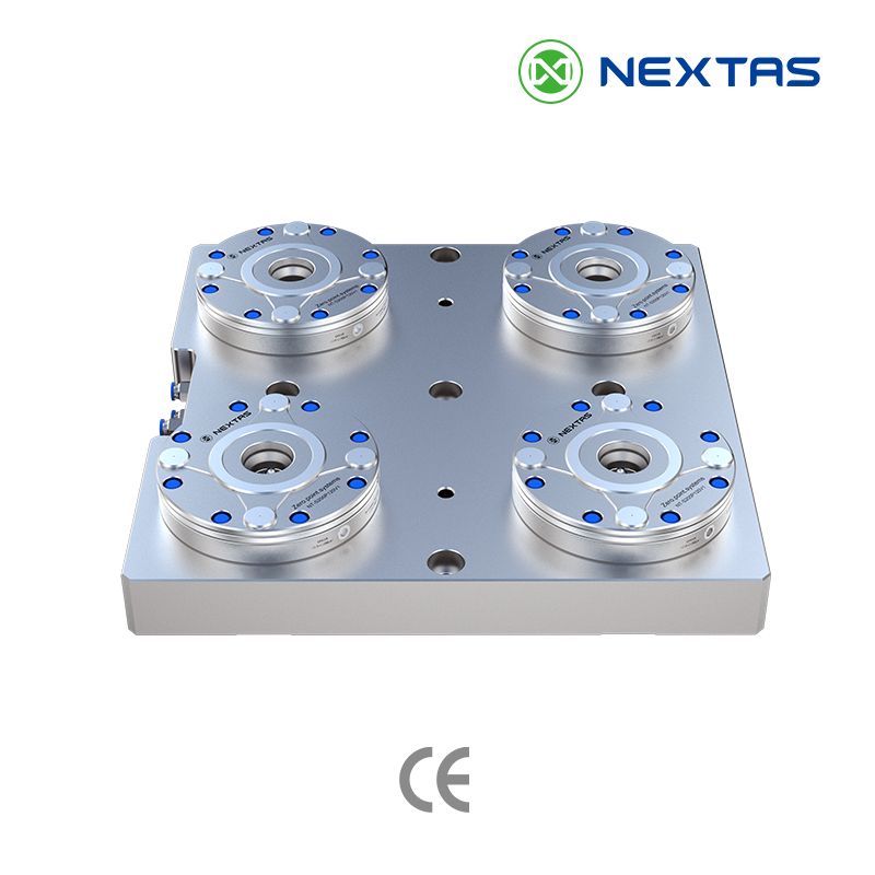
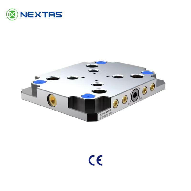
A datum system is the locating set around that place. One face on a drawing is not yet a system.
The quote says “zero point,” the drawing says “zero reference,” and the fixture note says “datum system.” Those are not three spellings of one part.
This page owns the locating set. The zero point is the quick-change joint. The zero reference point is the feature you name. The short map only points.
Matched body and pallet
A datum, where these pages define it, is the reference used to locate and measure. A datum system is the hardware that puts that reference back: the faces you locate from, the pull-down direction, a rotation stop, and the mating parts. The system page asks for a fixture layout that shows receiver spacing and the datum scheme. One face on a drawing is not yet a system.
The selection guide’s matched form is a base and a carrier made for each other. That is the sense in which BDS is a datum system. The BDS page says the datum body is the clamping receiver mounted on the machine or fixture base. The datum pallet is the mating carrier for repeat transfer and automated handling. The body stays. The pallet moves. Keep the body and pallet in one family. The A024 versus B024 guide is the shortlist between those two BDS bodies. This page does not choose between them.

The BDS page lists repeatability below 0.003 mm and a clamping force of 60,000 N for A024 and B024 as selection references. Neither number is the cutting load your tool will apply, and the page does not treat either as a guarantee for every assembled system. The selected drawing and the agreed measurement conditions have to confirm the value that applies. Unlock air for those datum bodies is listed at 0.5–0.8 megapascals (MPa), and the page recommends clean, dry air. If a robot or the machine must release the body, write the shop’s air pressure beside that band. A manual plate publishes “no air supply.” A quote that needs this air band is not that plate. If the fixture is wide and the cut is heavy, leave BDS and open the receiver-size guide.
Each machine and each CMM has its own coordinate frame. A chuck, a receiver, or a BDS pair can give you physical reference features. They do not line those frames up by themselves. The wire-EDM to CMM article is about qualifying that kind of transfer on E-Series holders. Open it when the part moves between stations. It is not a second definition of the zero-point plate.
Pull studs are not program zero
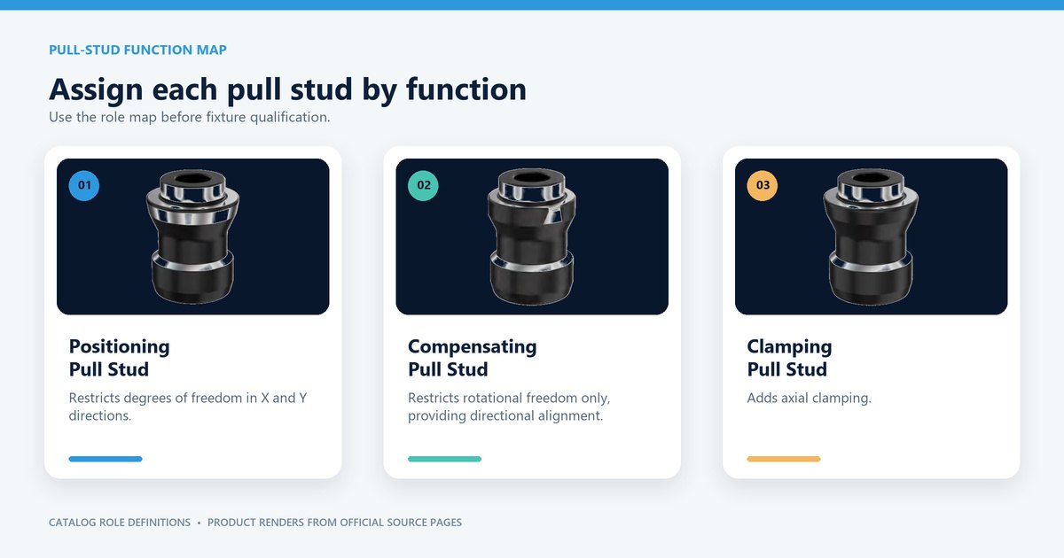
Pull studs are the pins on that joint. They are not the program zero. The system page treats the stud as the precision interface between the fixture and the receiver, and it separates standard, compact, and anti-rotation styles by clearance and by what the datum needs. The role map below labels three further jobs on the studs themselves. Positioning restricts movement in X and Y. Compensating restricts rotation and sets a direction. Clamping adds the pull-down. Do not buy one style for every hole. Copy the mix on the module drawing. Stocking replacements is a different job; that list lives on the spare-parts guide.
A Manual & Automatic Pallet Changers moves the pallet. It does not choose the datum system, and it does not line the CNC frame up with the measuring machine.

Fields the quote still needs
Name the locating set. For BDS, write the body and the pallet as a pair. A receiver stack belongs on the zero-point page.
- Datum system: the locating set. For BDS, name the body and pallet as a pair. For a receiver stack, name the stud style and whether rotation has to be locked. Write unknown where the drawing is open.
Questions before you name the locating set
The pallet drawing says A024 or B024. Can I order a 96 mm plate?
No. Order the matching BDS body with that pallet. A 52 mm or 96 mm code is the bolt-down plate, and an A024 pallet does not seat on a B024 body.
Someone wrote “below 0.003 mm” with no model name. What do I do with it?
Send it back. That bare line can be the V1 receiver listing or the BDS selection reference, and those are not the same acceptance. Put the model code in the same cell as the number, then agree how you will check it.
If the drawing only says “datum,” which lines are still open?
Both the joint and the feature. “Datum” does not name a face, pad, bore, or plane, and it does not name a receiver, a plate, or a BDS pair. Leave both lines unknown until the drawing shows them.
Does a pallet changer choose the datum system?
No. The changer moves a pallet. The datum system is the hardware that brings the reference back: a body that stays and a pallet that moves, or a stack of receivers. Keep the body and pallet in one family. An A024 pallet does not seat on a B024 body. The changer does not make that pair.
Before a model number
Attach the machine-table drawing
The table drawing shows whether the quote lines fit the machine. Send it with the quote.
Send the table drawing