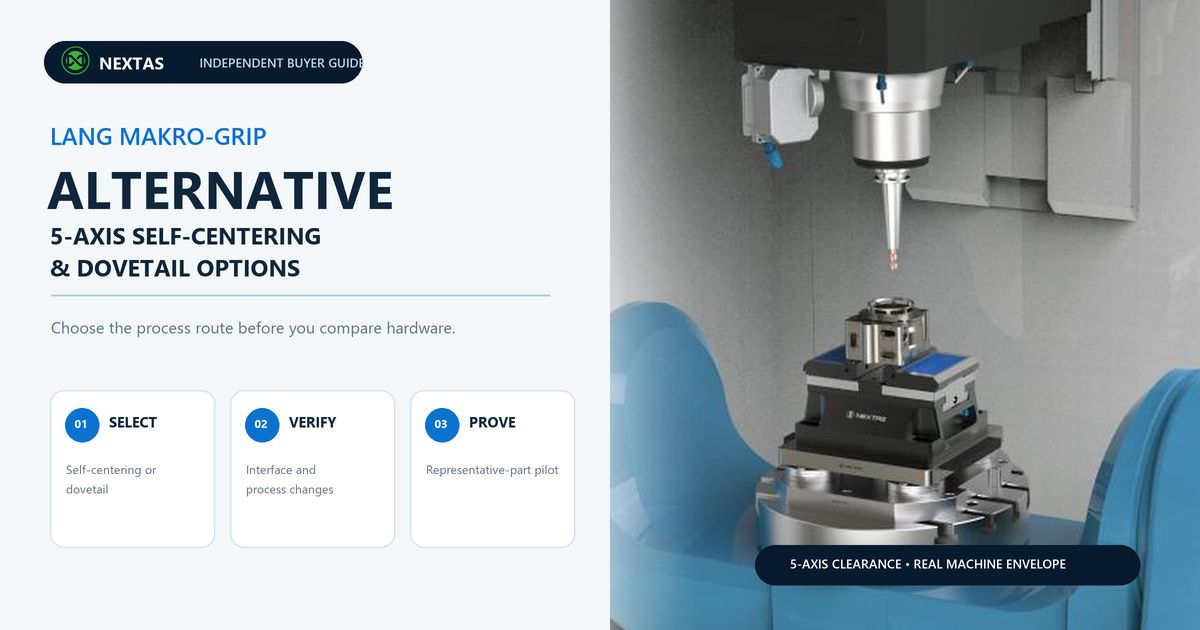
A search for a LANG Makro-Grip alternative often begins with price, lead time or a second-source request. The real purchasing decision is broader: will you keep a prepared grip feature on every blank, move to a self-centering jaw process, or change only the upper workholding while retaining the existing zero-point foundation? Those choices affect blank preparation, CAM, datum transfer, inspection and operator work. Comparing a catalog photograph or headline clamping force will not answer them.
Start with the purchasing fork, not the brand name
Use a self-centering vise when the incoming blank has two controllable opposing faces, width varies across the family, a centerline-based setup is valuable, or different hard, serrated or machinable jaw strategies are part of the process. Use a pneumatic dovetail fixture when a consistent 45-degree sacrificial feature can be prepared, the concentrated grip zone improves five-side access, and single- or multi-station loading justifies the extra preparation operation.
Do not combine that upper-workholding decision with the receiver or pallet decision. If the vise route is settled and the open question is the 52/96 zero-point layer, use the separate LANG Quick-Point alternative guide. A plate interface and a part-gripping method solve different problems.
| Buyer condition | Self-centering route | Dovetail route | Evidence to verify |
|---|---|---|---|
| Incoming blank | Two controllable opposing faces; jaw choice can absorb family variation | Blank can receive a repeatable 45-degree sacrificial feature | Blank drawing, saw/forge/cast condition and lot variation |
| Datum logic | Fixture centerline can support width changes | Prepared profile and locator establish seating; it is not self-centering | Datum scheme, probe cycle and CMM alignment |
| Five-side access | Good when jaws, body and holder are collision-checked | Concentrated lower grip often leaves more side access | Real holder, tool, fixture and rotary envelope in CAM |
| Stock preparation | No dovetail operation; soft jaws may still need machining | Adds cutter, profile inspection, deburr and cleaning controls | Op 10 cycle, profile method and scrap plan |
| Part-family flexibility | Strong where widths and gripping faces vary | Strong where one controlled profile can be standardized | Minimum and maximum part list, not one showcase part |
| Station strategy | Usually one vise per station; pallet layouts remain possible | Single-station P50 or three-station P90 path | Table area, loading access, batch mix and takt |
| Automation | Manual and powered families require configuration-specific checks | P50/P90 are pneumatic; air and confirmation scope must be defined | Air, PLC, sensors, fail-safe state and gripper access |
Route A: size a NEXTAS self-centering vise to the part family
Start with the complete part list: minimum and maximum blank width, gripping-face condition, material, expected cutting load, tallest tool assembly and worst rotary angle. A self-centering mechanism keeps the two jaws moving symmetrically around its mechanical centerline; it does not make an asymmetric casting or rough forging geometrically true. Your datum and probing plan still have to manage blank variation.
For the standard quick-change vise route, the NEXTAS product page lists 52 and 96 families. The published values below are family-level selection inputs, not guarantees of finished-part accuracy. The repeat-positioning value applies at the vise level and must be confirmed for the selected model, mounting stack and inspection method.
| Published family input | 52 family | 96 family |
|---|---|---|
| Spigot distance | 52 mm | 96 mm |
| Vise-level repeat positioning | <0.02 mm | <0.02 mm |
| Published clamping force / input | 14,000 N at 70 Nm | 20,000 N at 100 Nm |
| Jaw width / body height | 77 mm / 87 mm | 125 mm / 111 mm |
| Listed maximum-range options | 95, 120, 160 or 200 mm | 150, 200, 250, 300 or 350 mm |
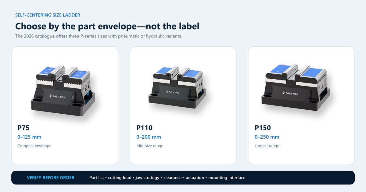
For powered cells, the 2026 catalogue also presents P75, P110 and P150 pneumatic-centering sizes, with pneumatic and hydraulic variants. Treat the size ladder as a shortlist, not an approval. Ask for the selected model drawing, jaw stroke, clamping-force basis, actuation conditions, mass, sensor options and exact lower interface. If the jaw and clearance decision needs more depth, use the 5-axis self-centering vise guide after this conversion review.
Route B: use a prepared dovetail when access earns the extra operation
The dovetail route moves work from the fixture setup into blank preparation. A controlled 45-degree feature is machined into sacrificial stock, inspected and deburred before loading. That extra operation can be worthwhile when it concentrates the grip near the bottom of the blank and releases more of the sides for machining. It is a poor trade when raw material is inconsistent, there is no stable prep operation, or the sacrificial zone conflicts with the finished geometry.
The NEXTAS NT-S500P50 is a single-station pneumatic fixture with published 4 kN clamping and <0.02 mm repeat positioning. The NT-S600P90 is a three-station pneumatic route with published clamping above 2.5 kN and a listed load limit of 30 kg per station; do not apply the P50 repeat figure to the P90 without written confirmation. The shared 6583-Z4 through Z16 jaw series lists widths of 10.5, 14.5, 18.5, 26.5 and 34.5 mm across different blank envelopes.
Do not copy a universal dovetail depth from a generic article. The correct preparation depends on the selected jaw, material, blank stiffness, cutting load and supplier drawing. Put the angle, cutter, profile dimensions, inspection method, edge condition and permitted grip marks into the approved process sheet. A consistent profile matters more than a familiar brand label.
Review what changes around the fixture
A migration can fail even when the new fixture itself is capable. Review the whole route from raw stock to final inspection and assign an owner to every change. The table below is the practical difference between a procurement exercise and a controlled process conversion.
| Conversion item | Question to close | Required evidence |
|---|---|---|
| Blank preparation | Do saw-cut faces, jaw stock or a dovetail profile change? | Controlled blank drawing, cutter and inspection plan |
| Operation split | Does Op 10 create the grip feature and Op 20 remove it? | Updated route, cycle estimate and WIP identification |
| CAM and collision | Are the exact jaw, body, adapter, holder and rotary limits modeled? | Released fixture model and worst-angle simulation |
| Datum transfer | Which surface or feature carries location after re-clamping? | Probe logic, setup sheet and inspection alignment |
| Lower interface | Do stud spacing, shoulder, bolt pattern, Z datum and release method match? | Both underside drawings and a signed interface review |
| Cleaning and confirmation | Can chips block seating, and how is clamp state confirmed? | Work instruction, air/PLC scope and fault response |
Numbers such as 52 or 96 describe a family or spacing context; they are not proof that components from different suppliers interchange. Confirm stud position and geometry, locating shoulder, bolt pattern, stack height, Z reference, tightening or release method, air routing and collision envelope. Do not mix precision receiver, stud, pallet or vise components unless the configuration is specifically reviewed and approved.
Prove the route on one representative part
Choose a part that exposes the real risk: the widest blank variation, the longest overhang, the heaviest roughing cut, the tightest datum transfer or the worst rotary tilt. A convenient demo part can make both routes look good while proving nothing about production. Freeze the proposed fixture model, jaw or dovetail profile, adapter, fasteners, actuation conditions, tool list, material and CAM revision before the test.
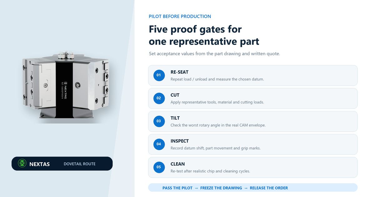
- Measure re-seating before cutting. Load, unload, clean and re-load the same controlled blank several times. Measure the datum chosen for the production process, not an easy surface that does not influence the part.
- Run representative cutting. Use the intended material, tool assembly, feeds, speeds and high-load operation. Inspect part movement, grip marks, jaw or profile condition and any loss of seating after the cut.
- Prove the worst rotary angle. Simulate with the released model, then use a controlled machine prove-out. Check spindle nose, holder, tool, part, jaw, body, hoses and table limits—not only the cutter tip.
- Repeat after realistic cleaning. Include chips, coolant and the planned operator method. A pristine metrology-bench result does not prove shop-floor re-seating.
- Record the decision. Compare results with buyer-defined drawing and process criteria. If accepted, freeze the model, interface drawing, jaw/profile specification, torque or air conditions, setup sheet and inspection method.
There is no responsible universal pass value for finished-part capability, grip marks or movement. Set those limits from the part drawing, material, risk and written quotation. Published fixture repeat positioning is one input; it is not a guarantee for the complete machine, tooling, blank and cutting process.
Compare ready-to-cut cost and quote scope
Do not compare fixture hardware alone. A self-centering quote may need jaws, spigots or adapters, actuation, sensors, CAD, inspection evidence and initial spares. A dovetail quote may also need jaw sizes, the approved cutter/profile specification, pneumatic controls, station accessories, prep inspection and spare wear items. Ask every supplier to state inclusions, exclusions, lead time, drawing approval, pilot support and the point at which the item is ready for production.
Ready-to-cut cost = hardware + engineering and adapters + blank preparation + qualification + installation + initial spares + expected operating time
A lower fixture price can lose its advantage if it adds an unstable preparation operation. A higher initial price can still be justified if the pilot proves less setup labor or better station density. Make those effects visible with your own cycle and labor rates; do not accept a universal savings claim.
Build the shortlist from the part, then request a quote
Shortlist a self-centering vise when centerline logic, varying widths and jaw flexibility are the strongest needs. Shortlist a dovetail fixture when a controlled sacrificial feature and five-side access are worth the added prep. If neither route can pass the interface and pilot review, keep the current process or engineer a custom fixture rather than forcing a catalog substitution.
For an engineering review, send the representative part drawing and STEP file, incoming blank condition, material, annual and batch quantity, machine and rotary-table model, current fixture underside or interface drawing, tool and tilt envelope, actuation needs, acceptance targets and photos of the existing process. That package lets NEXTAS return a configuration and assumptions that can actually be tested.
Convert a real process
Request a self-centering or dovetail route review
Send the part and blank files, machine/table details, current underside drawing, quantity and acceptance target. NEXTAS can review the route, interface and pilot scope before quoting production hardware.
FAQ
Is a NEXTAS option a drop-in replacement for LANG Makro-Grip?
No drop-in claim is made. NEXTAS options are separately engineered workholding routes. Verify the selected fixture drawing, mounting pattern, locating shoulder, Z datum, stack height, actuation, release method and machine envelope before ordering.
When should I choose a self-centering vise route?
Choose it when the blank has two controllable opposing faces, width changes across the part family, a centerline-based setup is useful, or the process needs a flexible serrated, hard or machinable-jaw strategy without adding a prepared dovetail to every blank.
When should I choose a dovetail fixture route?
Choose it when the blank can receive a consistent 45-degree sacrificial grip feature, five-side tool access is the priority, and the extra stock-preparation operation is justified by the intended part family, station plan and pilot result.
What should I send for a LANG Makro-Grip alternative quote?
Send the representative part drawing and STEP file, incoming blank condition, material, annual and batch quantity, machine and rotary-table model, current fixture underside or interface drawing, tool and tilt envelope, actuation needs, acceptance targets and photos of the existing process.