
Should you bolt receivers into the T-slots you already have, cover the table with a sub-plate, or use a grid-plate that can still take strap clamps? That is the real choice when you add zero-point clamping to an existing mill. The studs and receivers can belong to the same family. The layer under them is what changes leftover tool height, chip load, and what you can still clamp next month.
A receiver is the base unit on the machine. A pull stud is the hardened pin on the fixture. When the stud seats, ground faces inside the receiver set X, Y, and Z. The clamp then pulls the stud down. It does not “find” location by tightening T-nuts.
This guide compares three ways to put that interface on an existing T-slot table. Use it to pick which drawings to review. It does not approve a cut, a payload, or a plate thickness before those drawings exist.
Why the table layer decides the payback
Time the current fixture change before buying a table layer. Include table cleaning, T-nut placement, vise alignment and work-offset checks. Record how often rush jobs interrupt that sequence. These measured delays show which work a retrofit could remove.
Planning example, not a customer result: a fixture swap that takes 30 minutes, done three times in a shift, is 90 minutes of spindle wait. At a billed rate of $100 per hour, that wait is $150 of lost machine time that day. Replace the minutes and the rate with your own shop numbers. Do not treat this as a promise from a plate catalog.
Matched studs can support repeatable reseating, but they do not establish a fixture-change time. Measure the complete cycle on the actual machine: release, unloading, cleaning, reseating, clamping, datum checks and readiness to resume cutting. Compare that measured time with the current process using the same start and end points; do not infer a time saving from a clean-interface catalog value.
If the next question is air entry rather than the plate style, continue with the side-inlet routing guide after this shortlist.
Location and clamp are not the same job
On a plain T-slot table, the same bolts often locate and hold the fixture. As they tighten, the body can shift. On a zero-point stack, the seat sets the datum. The clamp only keeps the stud pulled down.
Two common clamp styles appear on retrofit jobs:
- Manual plates: a wrench or quick lock drives the internal lock. No shop air is required at the plate.
- Air or oil release: On a documented spring-clamped model, air or oil releases the stud. Confirm mechanical retention and the response to loss of supply from the selected model drawing and circuit. Spring retention alone does not validate a safe machine state. Assess the complete machine or cell, including stored energy, loaded parts, feedback, interlocks and restart behavior, and accept the required fault and safe states before operation.
NEXTAS manual plates in the 52 mm and 96 mm families are listed at less than 0.005 mm repeat positioning. The listed V1 receiver models on the zero-point systems page specify repeatability strictly below 0.003 mm; V2 repeatability must be confirmed from the selected model drawing. Those figures belong to a clean, matched interface. They are not a finished-part tolerance, and they are not proof that every mounting method will measure the same on your machine.
52 mm and 96 mm are mounting pitches, not load classes. Check receiver size, stud geometry, contact span, load path and the approved force and moment limits. A 52-to-96 mm adapter is only a candidate after its mating and mounting drawings match. Add it to the installed height and clearance check.
Option 1: bolt receivers into the T-slots
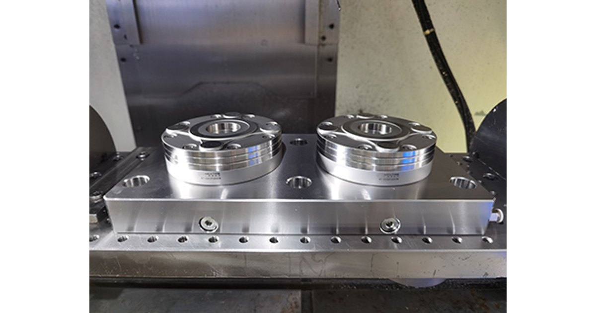
Direct mounting uses one receiver, a two-station block, or a small four-station plate bolted into the table channels. Ground keys, often in a 20H7 slot, can follow the center T-slot so the block stays parallel to X travel. Cap screws then pull into T-nuts. If the block has no keys, you still indicate it once during install.
Use this first when leftover tool height is tight, the machine is small, or you only need one or two vises in known places. A low block can leave more room for a long drill or a 4th-axis package. You also avoid buying a plate the size of the whole table.
The cost is protection and later moves. Open T-slots pack with chips and coolant. If the next job needs the block in a new place, you unbolt it, scrape the table, reset T-nuts, and indicate again. Air hoses for release modules often cross the work zone unless you plan a guarded path.
Treat a direct-mount block as a local station, not as a new machine table. If you expect to move it every week, the time you save on fixture swaps can disappear in table work.
Option 2: cover the table with a sub-plate
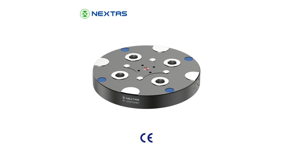
A sub-plate is a thick, ground plate that covers most or all of the machine bed. It is usually cast iron or treated steel. Receivers sit in bored pockets. On many air or oil plates, supply lines are drilled through the plate so one edge manifold feeds every station. That keeps hoses out of the chip stream.
Use this first when you run heavy cuts, want the original table protected, or already know most jobs will land on zero-point pallets. The extra mass can help damp chatter. The cover also keeps chips and coolant off the factory casting.
The tradeoff is height and weight. A plate thick enough for stiffness and internal lines uses Z travel that a small vertical mill may not spare. The same plate can be too heavy to lift off without a crane, so treat it as semi-permanent. If you still need the original T-slots every month, a full cover is the wrong layer.
Ask for the installed height of the selected plate plus receivers, not a generic “40 to 75 mm” guess. NEXTAS can only confirm stack height from the model drawing and your table.
Option 3: use a hybrid grid-plate

A hybrid grid-plate still covers the table and still holds zero-point receivers at a set spacing, often 96 mm. The rest of the face has a hole pattern, commonly on a 40 mm or 50 mm pitch. Hardened bushings locate. Threaded inserts, often M12, take strap clamps, toe clamps, or stops.
Use this first in a high-mix shop. Standard vises and pallets can snap onto the receivers. An oversized casting that does not fit a pallet can still sit on dowels and clamps in the grid. Riser blocks and 96-to-52 adapters also bolt to the same face.
The extra machining raises the plate cost. Unused holes collect chips unless you fit flush plugs. Height sits between a low T-slot block and a very thick armor plate, but you still have to read the selected drawing. Do not assume every grid-plate leaves enough daylight for a long tool.
If the mix is really four vises on one known plate, compare the separate four-station layout guide after you decide that a plate, not loose blocks, is the right layer.
How the three options compare
Repeat seating at a clean, matched interface can be in the same published class for all three. The mounting method still changes height, chips, mix, and plumbing. Read across one row at a time. Then check the selected drawing rather than copying a column as an order.
Planning comparison only. Force, height, and reseat values belong to the named model drawing, not to this table.
| Check | T-slot receivers | Full sub-plate | Hybrid grid-plate |
|---|---|---|---|
| How it mounts | Bolts into existing T-slots | Covers most of the table | Covers the table and keeps extra holes |
| Leftover tool height | Usually the lowest stack | Usually the highest stack | Usually in between |
| Table protection | Open slots collect chips | Best cover of the casting | Good cover; unused holes need plugs |
| Odd-shaped parts | Mostly standard vises or pallets | Needs zero-point pallets | Vises plus strap clamps |
| Air or oil lines | Often run in the work area | Can run inside the plate | Inside or outside, by design |
| First-fit shop | Small mill, tight Z, 4th axis | Heavy cuts and later automation | High-mix job shop |
There is no universal winner. A 5-axis trunnion that is already short on daylight often starts with a low T-slot block. A production mill that sees hard roughing often starts with a full plate. A toolroom that sees one-off castings often starts with a grid-plate. Write the constraint that matters most before you compare quotes.
Four checks before you drill or bolt
Match the plate metal to the table
Most mill tables are grey cast iron. A large steel or iron plate grows with heat at a similar rate. Bare aluminum on iron does not. It can also corrode in synthetic coolant.
Hypothetical calculation: assume the selected material pair differs in thermal expansion by 12.5 × 10⁻⁶/K. Across 800 mm with a uniform 12 °C rise, the difference is 800 × 12 × 12.5 × 10−6 = 0.12 mm. This assumes free, uniform expansion; it is not measured machine movement. Use verified coefficients for the actual materials and review temperature gradients, constraints and the locator drawing. For an aluminium plate, review coating, coolant exposure, bushings and inserts as separate design choices.
Do not lock a large plate on two rigid centers
Some approved multi-receiver layouts use one locating point, a second point that limits rotation while allowing expansion, and other points that pull down. Confirm the actual scheme, pin roles, fits and clearances from the selected assembly drawing. Do not assign these roles from receiver count alone. Check binding and datum movement under the expected temperature and load.
Keep chips off the locating faces
A 0.02 mm chip under a seat can exceed a close part’s positioning allowance; assess it against the actual tolerance. Use only cleaning and protective features documented for the selected receiver; a wiper is not universal. Where the selected model supports an air-gap check, confirm the sensing locations, physical measurement scope, circuit and calibrated threshold. The signal can indicate the monitored seating condition; it does not prove that every stud is locked, that clamping force is adequate or that the complete cell is safe. Interpret pressure changes from the selected sensing circuit and validate fault interlocks before Cycle Start. Set the trip value from the selected hardware, calibrated sensing circuit and agreed fault tests.
Indicate the next job off the spindle
Offline preparation can move loading and alignment out of spindle waiting time. Accept the full swap sequence on the actual station: release, safe handling, cleaning, reseating, clamping, state checks, datum checks and readiness to cut. Measure it against the old process using the same start and end points. Calculate payback from the measured time, job frequency, staffing and quoted retrofit cost.
Send the table, the mix, and the height limit
For a first retrofit review, send this brief. It lets NEXTAS compare a T-slot block, a full sub-plate, and a grid-plate against the same machine instead of quoting the thickest plate by default.
- Machine: model, table size, T-slot pitch, and the leftover height from table to spindle nose with the longest tool you must keep.
- Jobs: how often fixtures swap, whether odd castings appear, and whether vises, pallets, or both must land on the same station.
- Load: fixture mass, part mass, and the main cut direction. Say “unknown” if a field is open.
- Utilities: whether shop air is available, whether hoses may enter the work zone, and whether you still need the original T-slots some days.
- Scope: candidate layer (T-slot block, full plate, or grid-plate), quantity, and which receivers, studs, or adapters must be on the quote.
Ask for the installed-height stack, the locator scheme for several receivers, and the cleaning or air-gap options that belong to the named models. The process owner still has to prove seating, clearance, and first-part inspection on the machine.
Questions before you choose the table layer
Do the three mounting methods all give the same accuracy?
They can share the same published reseat class at a clean, matched stud and receiver. The mounting method still changes height, chip exposure, and how the plate is constrained. Prove the complete setup on your machine; do not copy a catalog reseat value onto finished-part tolerance.
Will a full sub-plate always take too much tool height?
No. It is usually the tallest of the three layers, but the limit is your leftover daylight and the selected plate drawing. A small mill with long tools often starts with a low T-slot block. Confirm installed height before you order.
Can I still clamp an odd casting after a zero-point retrofit?
Yes, if you choose a hybrid grid-plate and keep unused holes plugged. Direct T-slot blocks and many full sub-plates expect vises or pallets that already carry studs. An oversized casting then needs a different clamp plan.
Do I need shop air to retrofit an existing table?
No. Manual plates lock with a wrench and need no air. Air or oil is used to release spring-locked modules and to feed some sense circuits. Choose the utility from the selected model, not from the table-layer name.
Existing-table retrofit
Ask which table layer to review
Send the brief above and name the two layers you are considering. NEXTAS can compare leftover tool height, mix, and mounting space, then identify the model drawings and open questions for your quotation.
Discuss your table retrofit