
A miss on the second cut wastes more than a piece of stock. The first setup machines a raw blank. If you scrap that job, you lose metal. The second setup takes a part that already has hours, tools, and inspection behind it. If you scrap that job, you lose the cell's time as well.
Shops often call the first setup Op 10 and the second setup Op 20. The names vary. The risk does not. By the time the part reaches the second machine, it already has milled or turned faces, maybe a bore, and sometimes a stress-relief or deburr step. The fixture now has to sit on those finished features without marking them or bending them.
The usual failure is not a weak clamp. It is a fixture that treats the second operation as a gripping job. The real job is to copy the drawing datums from the first operation onto the second table, then hold the part there while the cutter works.
The short answer
Seat the part on the faces and holes cut in the first operation.
Use hard rests as locators. Clamp only to keep the part on those rests. Put each clamp over a solid rest, not over a pocket. If you have two finished holes, use one round pin and one diamond pin. Measure a key size while the first part is still clamped, then measure it again after you open the fixture. A jump means the clamp or the support is wrong.
Do not use leftover saw-cut edges as the locator. Do not use clamp squeeze as the locator.
Location sets the place. Clamping only holds it there.
A locator is a hard stop. It sets where the part sits. A clamp is a push. It keeps the part against that stop while the tool cuts.
If you rely on clamp friction to hold a finished part in space, the part can creep. A small slip does not look like much on the table. It shows up later as a tapered wall, an out-of-square bore, or a face that no longer matches the drawing.
The basic shop layout is 3-2-1. Three rest pads under a finished face set height and stop the part tipping. Two stops on a second finished face stop slide and spin. One stop on a third face stops the last slide. The clamps then hold the part against those six points. They do not replace them.
On a finished face, use a flat, hard rest pad with enough area that it will not dent the metal. If the face is a little wavy, a round rest button can still touch at one clean point. Cut a chip groove or a corner relief in the rest. A chip as thin as a hair under a solid pad will tilt every part in the batch.
Seat on the first-operation faces, not leftover stock
In the first operation the fixture often sits on a saw-cut edge, a casting skin, or a forged wall. That is fine for a roughing job. In the second operation the drawing usually wants a bore, a face, or a thickness from a datum that was cut in that first setup. Call that Datum A if the drawing does.
The second-op fixture must sit on that same datum. If you sit on an uncut outside wall instead, you stack the leftover stock error into every later cut. The part can look seated. The inspection report will still fail the drawing.

If the second operation is on a self-centering vise, the jaw face still matters. Smooth or soft jaws protect a finished face. Serrated jaws belong on a raw blank. That shortlist is in the jaw-selection guide. This page starts after those faces exist.
Two finished holes need two different pins
Two holes from the first operation make a repeatable second-op locator. Two tight round pins in those holes do not.
Hole spacing always varies a little within the drawing. Two full round pins fight that gap. The part binds on the way in. Operators then tap it off with a mallet and mark the bores you just paid to finish.
The shop fix is one round pin and one diamond pin. The round pin sits in the main hole and sets the two table directions. The diamond pin sits in the second hole and only stops rotation. It is cut back on the sides that face the other hole, so spacing error has room. Keep a tight fit on the sides that stop spin.
Make the round pin a little taller. The operator can drop the main hole first, then swing onto the diamond pin. That saves galling and speeds the load. If a nest can take the part backwards, add one offset pin or an uneven rest so the wrong load will not sit.
Clamp into the rest, not across a hollow
Clamp force has to beat the cut. Extra force does not make a better part. It bends a thin wall. When you unclamp, the wall springs. A bore that looked round in the fixture is oval on the inspection report.
Put the clamp over a solid rest. The load then goes straight down through the part into the pad. If the clamp sits to one side of the rest, it bends the span. If the first operation milled a pocket, do not squeeze that floor from above unless you add a support under it first.

On a finished face, use a wide, flat pad. A knife-edge strap will leave a mark. Soft contact pads in aluminium, brass, or a polymer such as Delrin or PEEK give before they dent steel. On a strap clamp, use a matching pair of spherical washers under the nut so the strap can tilt without loading one edge.
Thin rings and housings fail in a special way. A three-jaw chuck can squeeze a round part into a triangle while it is clamped. You machine that shape. Then you open the chuck and the bore is no longer round. Spread the grip. Soft jaws bored to the finished diameter, or an expanding mandrel inside a sleeve, spread the load. If the circuit allows it, drop the clamp force for the last finish pass.
Soft jaws are the workhorse for many second ops on a self-centering vise. Cut the pocket while the vise is already clamped on a spacer, at the same torque or pressure you will use on the part. Then remove the spacer. The jaw faces stay closer to parallel under load. That is a shop method. It is not a published NEXTAS accuracy figure.
Extra supports should touch, then lock
A long plate or a thin floor will chatter on three rest pads. Extra fixed pins are not the fix. They over-locate the part. The part then rocks on whichever pin is high.
A floating work support solves that. A light spring or low air extends a plunger until it kisses the underside. It does not lift the part off the real datums. After the main clamps seat the part, oil or a lock sleeve freezes that plunger into a rigid post. The post then takes cutting load without pre-bending the part.
Lock the extra supports after the main clamps. If you lock them first, they become a high point. The clamps then bend the finished part over that post. The second-op sizes are already lost.
A useful clamp order on a multi-clamp fixture looks like this:
- Set the part on the fixed locators.
- If the rest pads have air holes, check that the seat is closed. A drop in back-pressure means a chip or a tilt. That check can block Cycle Start. It is a process check. It is not a safety-rated stop unless the cell safety design says so.
- Let floating supports touch.
- Clamp in a balanced order.
- Lock the extra supports.
A custom hydraulic fixture can put that order into sequence valves. Do not copy a generic sequence onto an unreviewed circuit. The selected drawing still rules.
Which platform fits this second op?
The locator and clamp path come first. The platform comes second. Use the rows below as a first screen, not as an order list.
Planning screen only. Force, reseat, and range belong to the named drawing, not to this table.
| Setup | Use it when | Watch for |
|---|---|---|
| Soft jaws in a vise | Prismatic or turned parts, mixed lots, a nest you can recut | Cut the pocket under load. Jaws wear. Confirm the selected vise drawing. |
| Dedicated hydraulic fixture | Repeat housings, thin walls, a clamp order you must repeat | Needs a drawing review and a circuit the shop can service. See the hydraulic fixture guide if volume and support are the open question. |
| Vacuum chuck | Thin flat plates and light finish cuts | Poor against a heavy side cut. Keep roughing light. |
| Zero-point pallet | You want to load the second op offline and drop the pallet in | Confirm the studs and receivers. Listed reseat is pallet-to-receiver, not a part-tolerance promise. |
If the open question is still manual, air, or oil on the clamp itself, use the load and utilities guide after this page. That page chooses the actuator. This page chooses how the finished part sits.
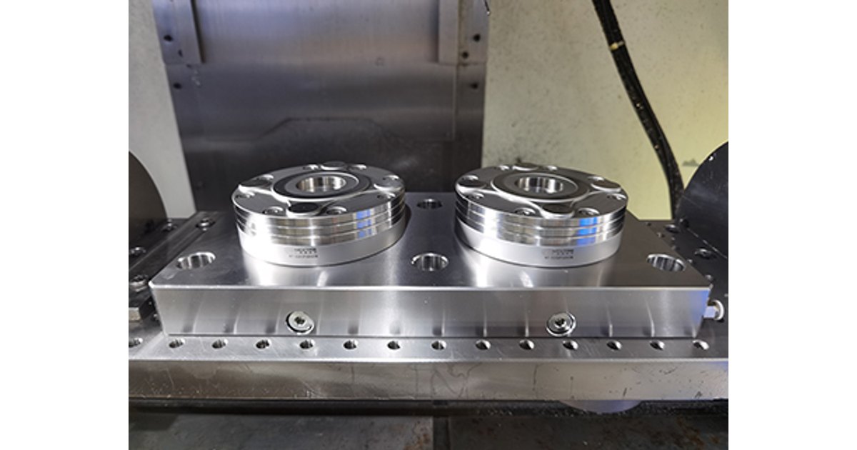
A zero-point receiver keeps the machine datum while you load the next pallet at the bench. Selected NEXTAS receiver families list reseat closer than 0.005 mm. That figure is the pallet-to-receiver joint on the named drawing. It is not a promise that the finished part will match the print. Dirt, a bent stud, or a weak fixture on top of the pallet can still move the cut.
Check the first finished part before you run the batch
Write these checks into the setup sheet. They are not extra ceremony. They are how you catch a bent part before you scrap a tray.
- Read the first-op inspection. Confirm the locating faces, holes, and thickness sit in the band you planned.
- Check that the physical rests match the drawing datums, not a handy leftover edge.
- Check tool and spindle clearance against clamp straps and fixture walls, including any tilt angle.
- Wipe the part and the rests. Blow the air-purge holes if the fixture has them.
- Clamp in a balanced order with a set torque or a set pressure. Do not “snug it until it feels right.”
- Probe the drawing datums to set the work offset. Do not pick a convenient corner.
- Program the heavy cut so the force pushes into the locators, not out toward the clamp fingers.
- Measure a key size on the first part while it is still clamped. Unclamp and measure the same size at once. A jump is springback or leftover stress. Fix the fixture or the clamp force before you run the rest.
Let a hot first-op part cool to shop air before you clamp it for the second operation. If it shrinks in the fixture, you lock that stress in.
What to send for a second-op fixture review
NEXTAS can review locators, clamp path, and whether a vise nest, a hydraulic fixture, or a zero-point pallet is the right next step. It cannot approve a process from a photo alone, and it cannot promise a finished size before the drawing and the first-op faces exist.
- The drawing: datums, the second-op features, and any face that cannot be marked.
- The first operation: photos or a report of the locating faces, holes, and thickness as they leave that setup.
- The part: material, thin walls, rings, or a pocket that needs support under a clamp.
- The machine: model, table or pallet size, and whether a robot or a pallet pool waits on this station.
- The failure you see now: slip, marks, springback, bind on pins, or chatter. Say which. Say if you are unsure.
Write unknown on any line you cannot answer. A blank is easier to quote than a guessed datum.
If you still need a custom-fixture partner checklist, use the questions to ask before you order after this page. Those questions start with the supplier. This page starts with the part on the second table.
Questions buyers ask before they cut a second-op fixture
Can I locate the second operation from leftover saw-cut edges?
No. Seat the fixture on the faces, holes, or bosses cut in the first operation, the same datums the drawing uses. Leftover stock edges stack extra error into every later cut.
Why not put two round pins in two finished holes?
Hole spacing varies within the drawing tolerance. Two tight round pins bind. Use one round pin to set position and a diamond pin to stop rotation. Relieve the diamond pin on the sides that face the other hole.
How hard should I clamp a finished face?
Use only enough force to keep the part on the rests against the cut. Extra force marks the face and can bend a thin wall. After the first part, measure a key size clamped and then unclamped. A jump means the clamp is too hard or the support is in the wrong place.
Is an air-seat check a safety stop?
No. Air through a rest pad can prove the part is down and can block Cycle Start if a chip is trapped. That is a process check. Guarding and stop logic still belong to the cell safety design.
What should I send for a second-op fixture review?
Send the drawing with datums, photos or a report of the first-op locating faces and holes, the second-op features to cut, any face that cannot be marked, and the machine or pallet data. Write unknown where you do not have a number yet.
Before you cut the second-op fixture
Send the first-op faces, the drawing datums, and the surfaces that must stay clean
NEXTAS can review locators, clamp path, and whether a vise nest, hydraulic fixture, or zero-point pallet is the right next step. It cannot approve a process from a photo alone.
Discuss your second-op fixture